What a Cement Plant Conveyor Pulley Does
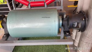
In a cement plant, raw materials, clinker, and additives move continuously between crushers, mills, silos, and kilns. The cement plant conveyor pulley is the cylindrical component that drives or redirects the conveyor belt at key transfer points. It is not a one-size-fits-all part: drive pulleys transmit torque, tail pulleys maintain belt tension and alignment, and bend pulleys change the belt path without driving. Each position demands a different design, and these roles are not interchangeable.
Construction and Surface Options
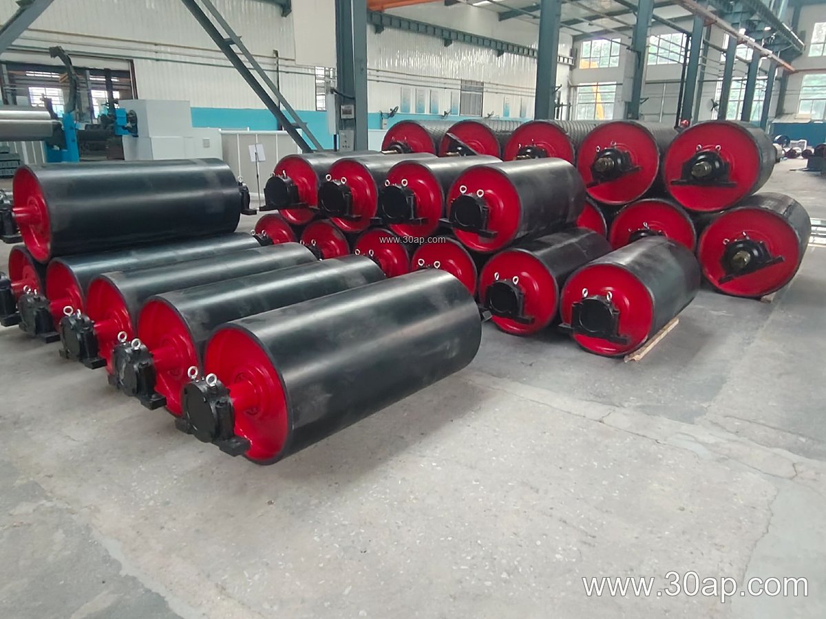
A typical pulley shell is welded steel, machined for balance, and fitted with shafts, bearings, and locking assemblies. Surface treatment depends on the duty. Plain steel is common for light contact, while rubber lagging improves grip in wet or dusty conditions. Diamond grooved lagging helps shed water and fines, and ceramic lagging suits high-wear zones. Lagging thickness is often 8 mm to 20 mm, selected according to belt tension and abrasion level.
Common diameters range from Ø200 to Ø1800, and face widths usually exceed belt width to keep the belt centered. For example, a B800 belt may run on a pulley with roughly 950 mm face width, and a B1200 belt on about 1400 mm face. Shaft diameters from Ø50 to Ø200 are typical, but final size is determined by torque and load, not by belt width alone.
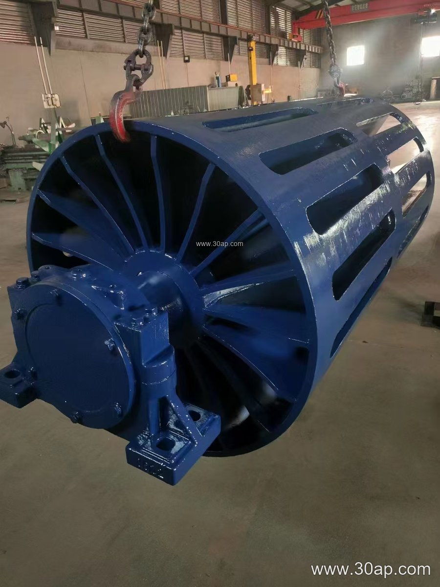
Where It Fits in the Cement Line
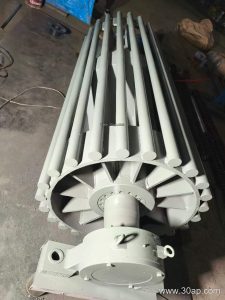
Drive pulleys are usually located at the head of a conveyor, pulling the belt toward the discharge. Tail pulleys sit at the feed end and often carry a self-cleaning or wing design to prevent material buildup. Bend and take-up pulleys appear along the return run, maintaining wrap angle and tension. In a limestone quarry or clinker transport line, a properly lagged drive pulley keeps the belt from slipping under heavy loads, while a wing tail pulley reduces sticking near the hopper.
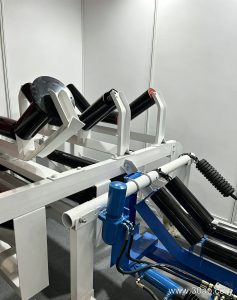
The pulley must work in harmony with the conveyor belt, idler rollers, and conveyor brackets. A misaligned pulley quickly wears the belt edge and loads the idlers unevenly. In dusty cement environments, sealed bearings and adequate lagging help extend service life.
Key Parameters for Buyers
When specifying a cement plant conveyor pulley, consider belt width, pulley diameter, face width, shaft size, lagging type, and bearing arrangement. The table below shows common reference ranges; actual values are determined by conveyor design.
| Parameter | Common Range |
|---|---|
| Belt width (B) | B400 to B2400 |
| Pulley diameter | Ø200 to Ø1800 |
| Face width | Belt width + 100–200 mm |
| Shaft diameter | Ø50 to Ø200 |
| Lagging thickness | 8, 10, 12, 15, 20 mm |
| Surface type | Plain, rubber lagging, diamond, ceramic |
For a heavy-duty application such as a primary crusher discharge, a B1400 × Ø800 pulley with 15 mm diamond lagging and a Ø160 shaft may be considered, but the final combination must follow the conveyor’s torque and tension calculations. A smaller B650 × Ø400 pulley with plain surface might suit a minor additive line. Avoid assuming that one belt width always pairs with one diameter.
Maintenance and Compatibility
Regular inspection of lagging wear, shaft alignment, and bearing condition prevents unplanned stops. In cement plants, heat and abrasive dust accelerate wear, so choosing the right lagging and keeping the pulley clean matters. The pulley also interacts with the conveyor belt type: a heat resistant conveyor belt may be needed near kiln discharge, while an abrasion resistant conveyor belt suits clinker handling. Matching pulley surface and belt cover helps avoid slip and premature failure.
At www.wodetransmission.com, you can find conveyor pulley references alongside conveyor belt and idler roller information for cement, quarry, and power plant applications. Whether the line uses an EP conveyor belt or a steel cord conveyor belt, the pulley specification should be confirmed against the actual load profile.