What an Adjustable Conveyor Bracket Does
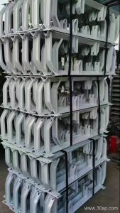
An adjustable conveyor bracket is the mounting component that carries idler rollers on a belt conveyor and lets maintenance staff change the trough angle or roller position without cutting and re-welding the frame. On a fixed bracket, the roller seats are welded in place, so the trough profile is locked in at the factory. The adjustable version uses slotted holes, pivoting arms, or bolted segment plates so the same bracket body can serve several trough angles and can be fine-tuned after installation.
In a quarry, a cement plant, or a power plant coal yard, the belt does not always run exactly as designed. Structure settles, rollers wear unevenly, and material loads shift. A bracket that can be re-set on site is often the simplest way to correct a trough that has become too flat or too steep. It also lets a plant keep one bracket family in stock instead of a separate welded assembly for every angle.
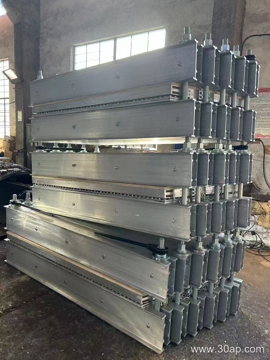
Construction and Mounting Position
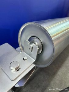
Most units are fabricated from angle steel, channel steel, or folded steel plate, with the roller seats drilled or punched to match common idler shaft ends. The adjustable feature usually comes from one of three designs: a slotted arc that allows the side roller arm to swing through a range of trough angles, a bolted hinge that fixes the arm at a chosen position, or a telescopic crossbeam that changes the distance between the center roller and the wing rollers.
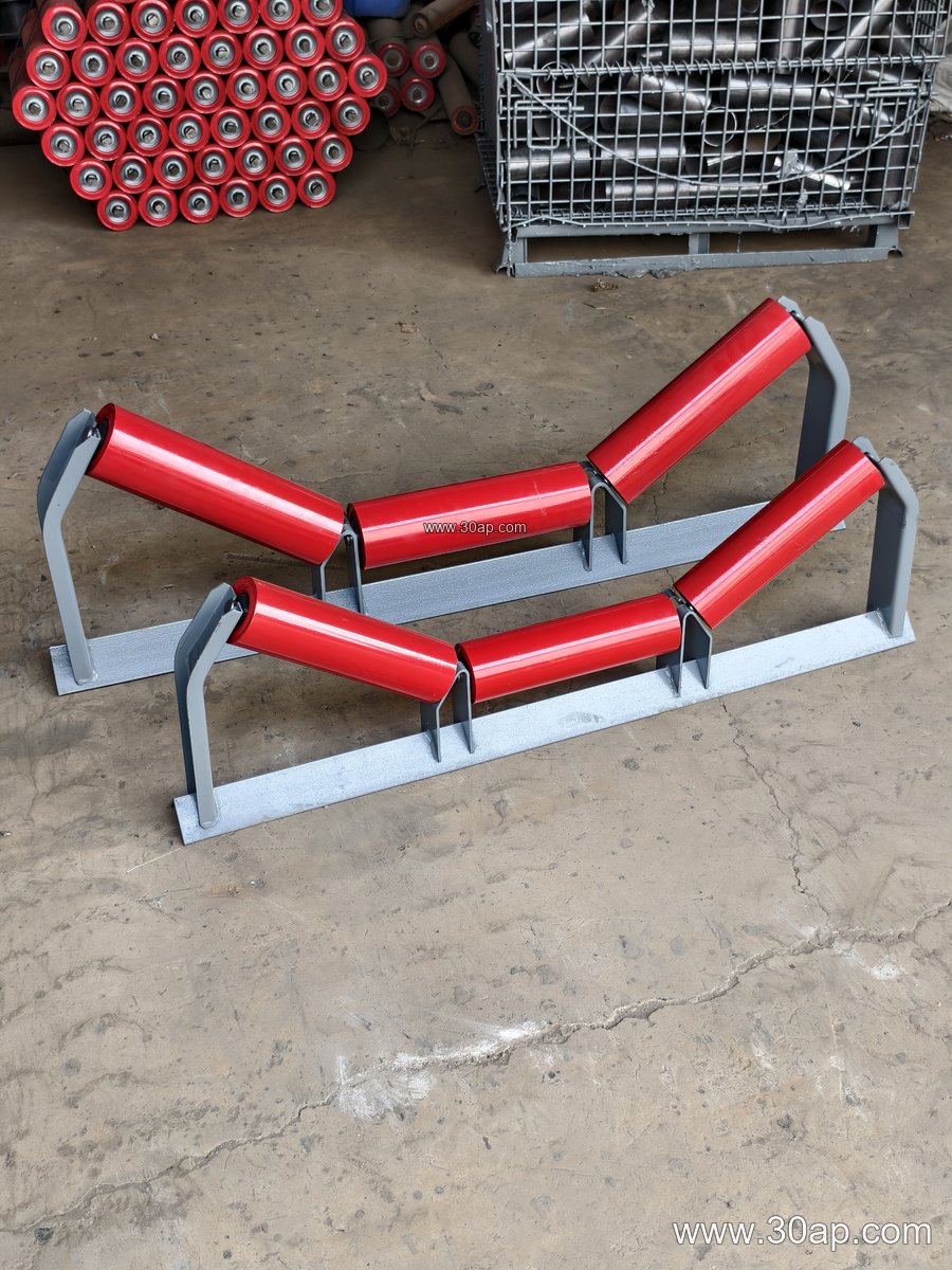
- Upper trough bracket – carries the three-roller trough set on the carrying side; the adjustable version sets the trough angle.
- Transition bracket – placed near the head or tail to ease the belt from flat to troughed; angle adjustment helps control edge stress.
- Return bracket – supports the return run, either flat or in a V formation.
- Self-aligning bracket – a related family that pivots to steer the belt; it is a different function from a plain adjustable trough bracket and should not be treated as a substitute.
Installation height and hole spacing are not universal. Crossbeam length and mounting hole pitch normally follow the belt width, the chosen trough angle, and the roller diameter, so the bracket should be ordered against the actual conveyor drawing rather than guessed from belt width alone.
Matching Belt Width, Trough Angle and Roller Diameter
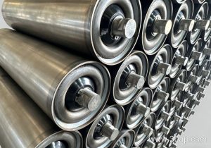
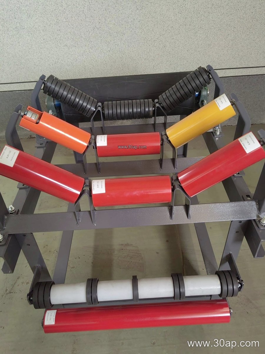
Trough angle and roller diameter are selected together with the belt, the load, and the transition length. Typical trough angles are 20, 30, 35, and 45 degrees, and an adjustable bracket can usually be set anywhere inside that range. A wider belt carrying a heavy abrasive load may suit 35 or 45 degrees with a larger roller, while a narrow belt on a short transfer may run at 20 or 30 degrees. Roller diameters such as Ø89, Ø108, Ø133, Ø159, and Ø194 appear across these duties, and the bracket seat must match the shaft end of the roller actually fitted.
The table below shows reference combinations only. They are examples of how the three values are usually written together, not fixed rules, and a given belt width can be paired with more than one angle or roller size.
| Belt width | Trough angle | Roller diameter | Typical setting |
|---|---|---|---|
| B500 | 20° / 30° | Ø89 | Light aggregate, small transfer |
| B650 | 30° / 35° | Ø89 / Ø108 | Sand and gravel line |
| B800 | 30° / 35° / 45° | Ø108 / Ø133 | General bulk handling |
| B1000 | 35° / 45° | Ø108 / Ø133 / Ø159 | Cement, coal, ore |
| B1200 | 35° / 45° | Ø133 / Ø159 | Heavy-duty main line |
| B1400–B1600 | 35° / 45° | Ø159 / Ø194 | Mine and port conveyors |
| B1800–B2200 | 35° / 45° | Ø159 / Ø194 | High-capacity bulk systems |
Forward tilt of about 1.5 to 2 degrees is sometimes built into the side roller seat to help belt training; check whether the adjustable arm keeps that tilt when the angle is changed.
Where It Fits in the Conveyor System
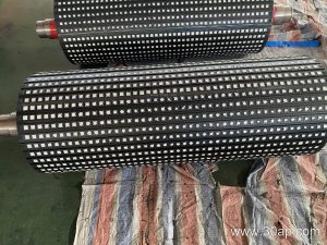
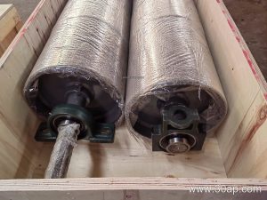
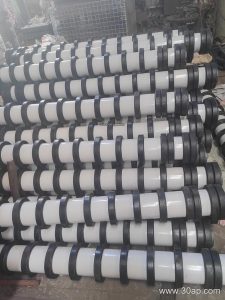
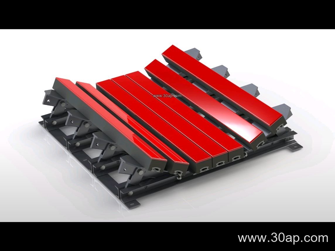
Adjustable brackets are common on the carrying side of troughed conveyors in stone crushing plants, limestone mines, iron ore handling, coal washing plants, and cement clinker lines. They also appear on fertilizer and grain silo conveyors where the belt profile must be set carefully to avoid spillage. The bracket works together with the conveyor belt, the idler roller set, and the conveyor pulley at each end; the pulley drives or redirects the belt, while the brackets shape the belt path between them.
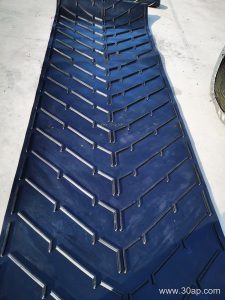
On a heavy-duty mining conveyor running an abrasion resistant conveyor belt, a correctly set trough keeps the load centered and reduces edge wear. On a heat resistant conveyor belt in a clinker or sinter line, the bracket must allow enough adjustment to compensate for thermal movement in the frame. In dusty coal mining conveyors, slotted parts should be checked for seized bolts, because a bracket that cannot move is no better than a welded one.
Buyer Checklist
- Confirm belt width, target trough angle, and roller diameter before ordering; supply the conveyor drawing if possible.
- State the roller shaft end type and whether forward tilt is required.
- Ask which materials are used (angle steel, channel, folded plate) and how the joint is locked after adjustment.
- Check that the adjusting range covers the angles you actually intend to run, not just the installed value.
- Plan a periodic inspection of bolts and slots, especially in wash plants and other wet, corrosive areas.
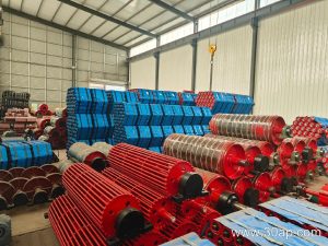
For matching conveyor belt, idler roller, and conveyor pulley data, keep the bracket specification tied to the same drawing set so the adjustable range stays useful over the life of the conveyor.