What a Head Pulley Assembly Does
The head pulley assembly is the drive point at the discharge end of a belt conveyor. It grips the conveyor belt, pulls the loaded strand toward the head, and throws material off at the transfer point. Because it transmits the drive torque, its design must match belt tension, shaft load, and the working environment. In a quarry or aggregate line, a head pulley assembly often runs under constant abrasive dust; in a coal mining conveyor it may need flame retardant components and robust sealing. The assembly is not a tail pulley or a bend pulley, and it should not be swapped with those positions without a full drive review.
Construction and Key Components
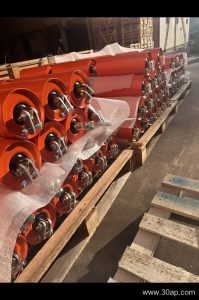
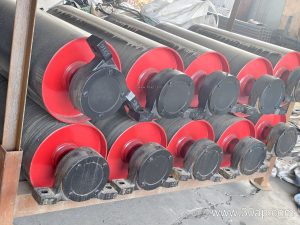
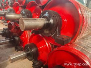
A typical head pulley assembly combines the pulley shell, shaft, hubs, bearings, bearing housings, and a lagging surface. The shell is usually welded steel, machined for balance, and fitted with end discs. Shaft ends are keyed or shrink-fitted to the hubs, and the shaft diameter is selected by torque and radial load rather than by belt width alone. Bearing housings may be bolted to a conveyor bracket or a tensioning frame. Drive connection can be direct through a gearbox coupling or through a shaft-mounted reducer.
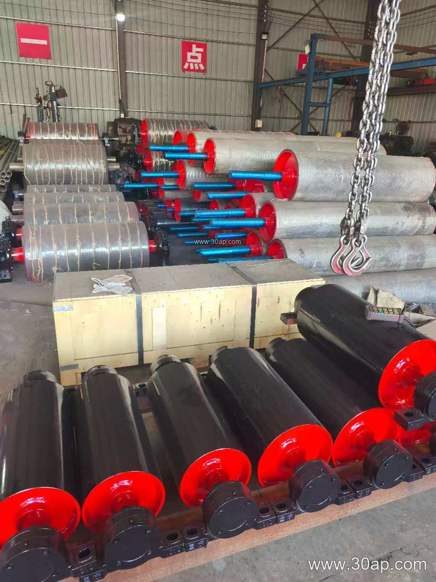
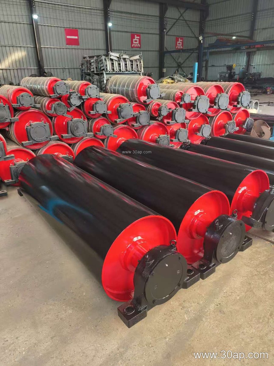
- Shell and hubs: carry belt tension and transfer torque.
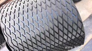
- Lagging: improves friction between pulley and belt; common forms include plain rubber, diamond grooving, chevron grooving, and ceramic lagging.
- Bearings and seals: protect against dust and water in crushing, screening, and power plant coal handling.
- Drive interface: couples the assembly to the gearbox or motor.
Where It Fits in Bulk Handling
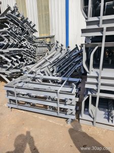
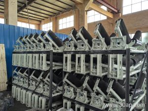
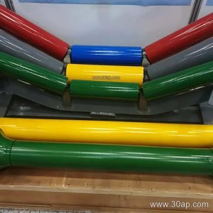
Head pulley assemblies appear in limestone mines, iron ore plants, copper concentrators, cement clinker lines, port bulk terminals, and tunnel spoil conveyors. In a sand and gravel plant they work with a heavy-duty conveyor belt carrying abrasive aggregate; in a steel plant they may handle sinter or coke. The assembly also interacts with the conveyor belt, idler roller, and conveyor pulley components along the same frame. A conveyor bracket supports the bearing housing, so alignment between bracket, pulley shaft, and gearbox matters for service life.
Matching the Assembly to the Belt
Belt width and pulley diameter are related through belt tension, wrap angle, and space limits, but there is no single diameter that fits every belt width. A B800 conveyor may use a Ø500 head pulley in one layout and a Ø630 or Ø800 in another with higher tension. The table below gives common reference combinations; final values should be confirmed by the conveyor designer.
| Belt width | Common pulley diameter | Typical face width |
|---|---|---|
| B500 | Ø315, Ø400 | about 600 mm |
| B650 | Ø400, Ø500 | about 750 mm |
| B800 | Ø500, Ø630 | about 950 mm |
| B1000 | Ø630, Ø800 | about 1150 mm |
| B1200 | Ø800, Ø1000 | about 1400 mm |
| B1400 | Ø1000, Ø1250 | about 1600 mm |
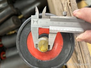
Shaft diameters commonly range from Ø50 to Ø200, but the correct size depends on drive torque and bearing span. Lagging thickness is often 8, 10, 12, 15, or 20 mm. For a high-abrasion aggregate conveyor, diamond rubber lagging is a frequent choice; for a coal mining conveyor, flame retardant belt and suitable lagging may be specified together. The head pulley assembly should also be checked against the EP conveyor belt or steel cord conveyor belt tension rating used on the conveyor.
Buyer Checklist
- Confirm the drive position: head pulley assembly, not tail or bend pulley.
- Provide belt width, belt type, and maximum operating tension.
- Specify lagging form and thickness if extra grip is needed.
- State the environmental conditions: dust, moisture, temperature, or oil exposure.
- Check bearing housing mounting and conveyor bracket dimensions.
- Review shaft diameter and keyway with the gearbox coupling.
For a reliable match, share the conveyor layout and belt data with the pulley supplier. The head pulley assembly is a drive component, so small changes in belt tension or lagging can affect the whole conveyor drive.