Understanding the Role of the Conveyor Self-Aligning Idler
In heavy industrial processing installations, keeping the main conveyor belt tracking correctly is essential for continuous production. When misalignment occurs, material spillage and edge wear quickly escalate. A specialized Conveyor Self-Aligning Idler actively corrects off-center running conditions before they cause structural damage. Unlike a standard idler roller that remains fixed in place, this pivoting assembly responds to lateral forces exerted by the moving belt, gently guiding it back to the centerline without requiring manual intervention.
Construction and Structural Design
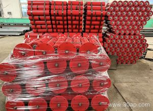
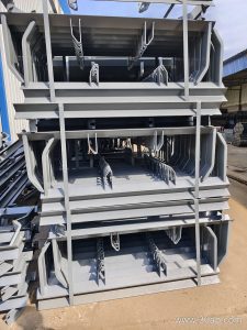
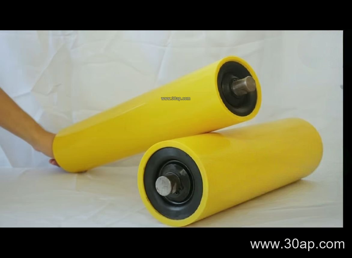
The mechanical assembly of a Conveyor Self-Aligning Idler typically consists of a pivoting upper frame, a central swivel pivot, and auxiliary guide rolls. When the running belt drifts sideways, it contacts the trailing side rolls, which causes the entire pivoting frame to swivel slightly. This angular adjustment creates a steering force that steers the belt back into alignment.
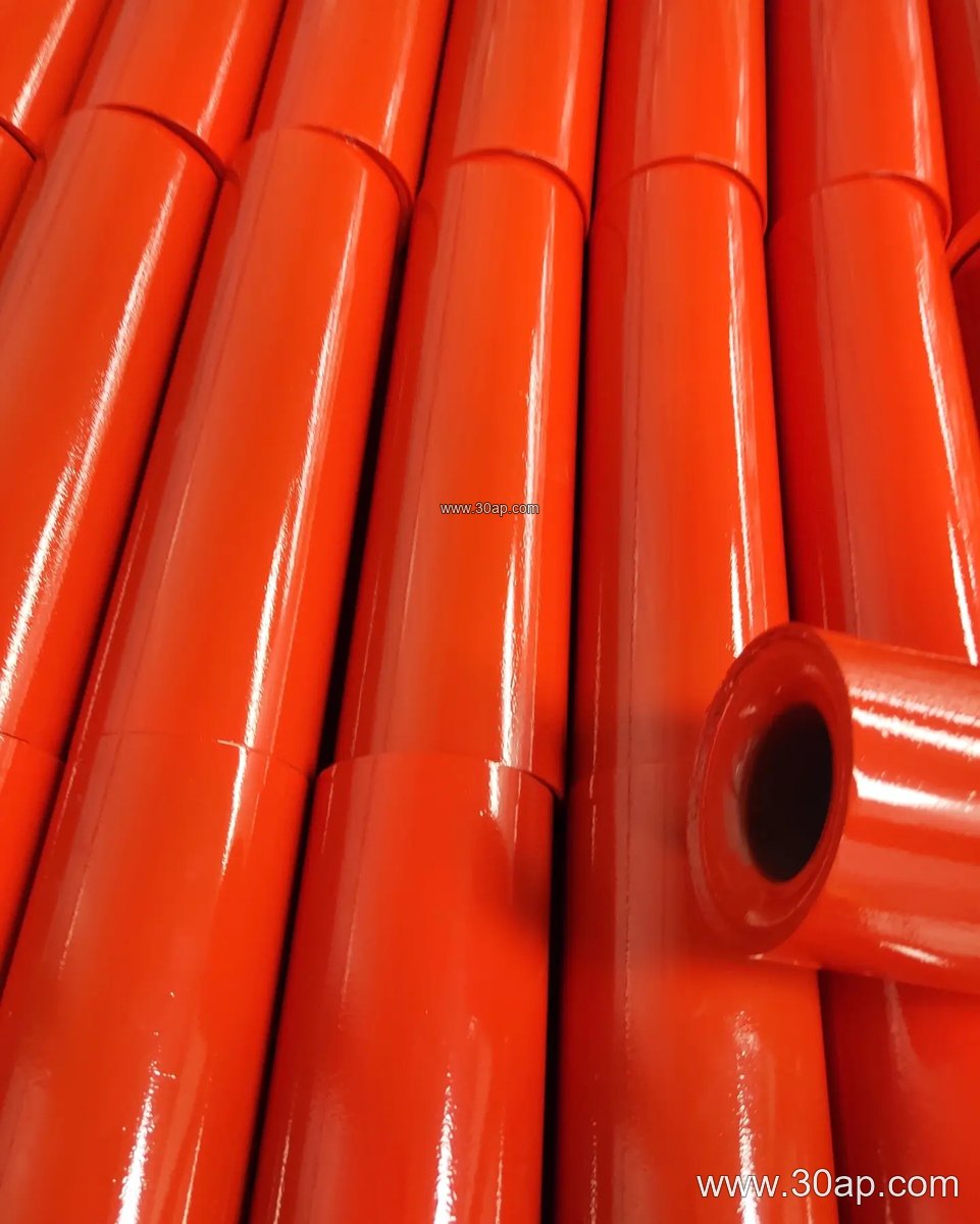
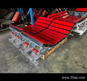
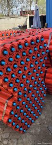
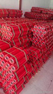
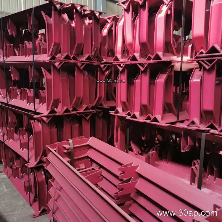
Manufacturers build these units to match various system layouts, often pairing them with a heavy-duty conveyor bracket for secure mounting to the stringer. The internal components rely on reliable bearings such as 6204, 6205, 6305, 6306, 6308, or 6310 to ensure smooth rotation under heavy loads. Depending on operational demands, the individual rollers can feature steel pipe, rubber ring, ceramic, or nylon surfaces.
System Integration in Cement Plants
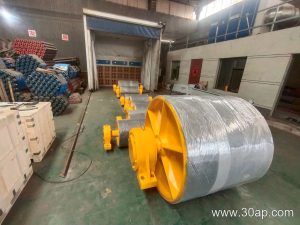
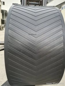
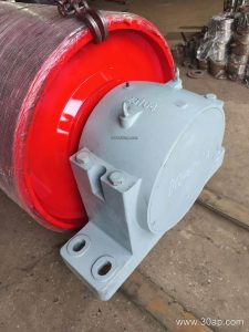
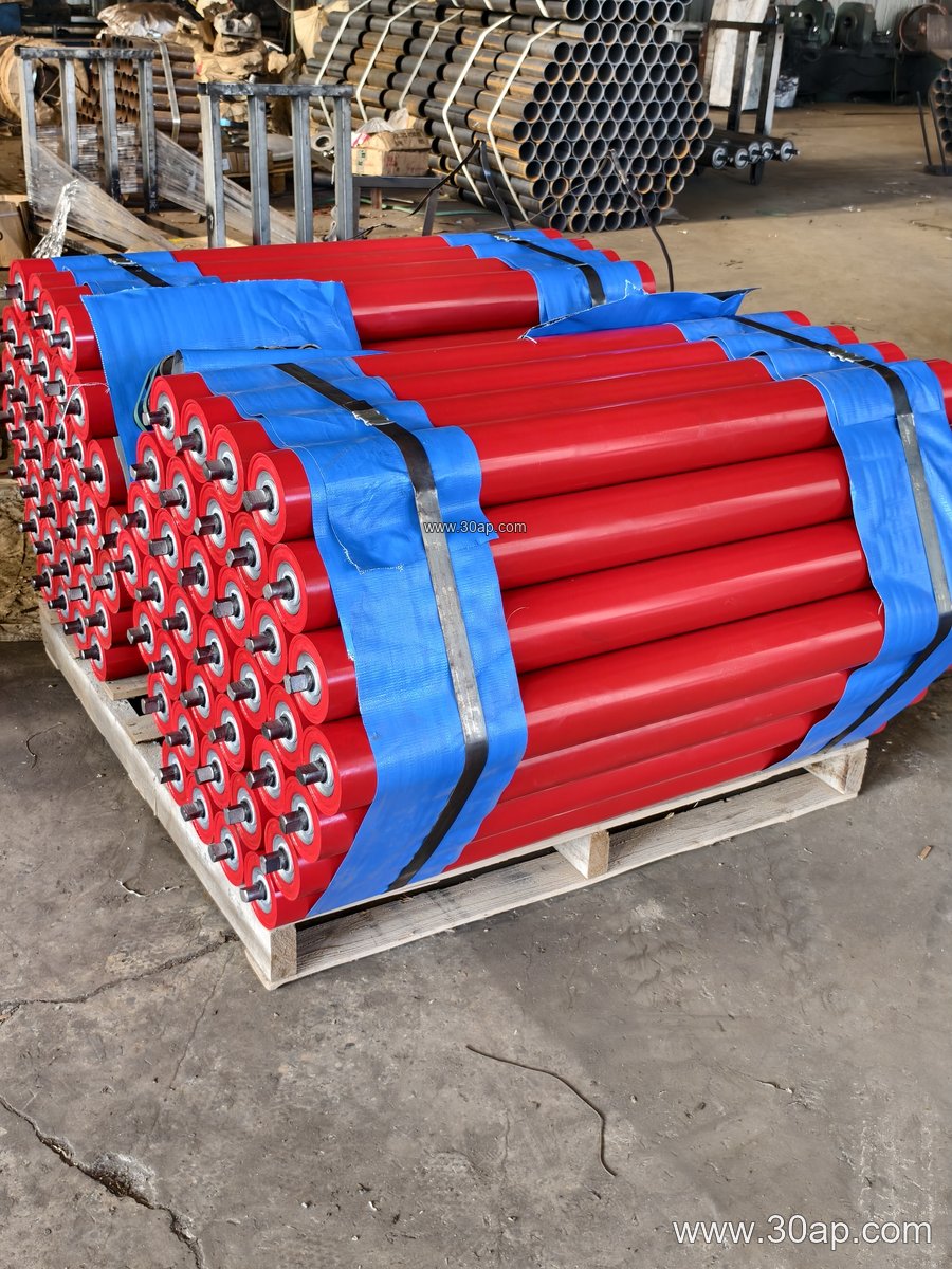
Cement plants present rigorous operating environments characterized by abrasive clinker, dust, and continuous heavy loading. In these facilities, a Conveyor Self-Aligning Idler is frequently installed along long overland spans and near transfer points where conveyor pulley assemblies change the belt direction. By maintaining proper tracking across these long stretches, the installation prevents uneven tension distribution. Operations working with an EP Conveyor Belt or a heavy Steel Cord Conveyor Belt rely heavily on these pivoting assemblies to compensate for thermal expansion, load shifts, and minor structural settling.
Reference Specifications and Dimensions
Selecting the correct unit involves evaluating the system bandwidth and expected load parameters. The following table outlines common reference specifications frequently encountered in industrial belt conveyor layouts:
| Bandwidth (B) | Roller Diameter (Ø) | Common Trough Angle | Bearing Options |
|---|---|---|---|
| B650 | Ø89, Ø108 | 30 Deg, 35 Deg | 6204, 6205 |
| B800 | Ø108, Ø127 | 30 Deg, 35 Deg | 6205, 6305 |
| B1000 | Ø127, Ø133 | 35 Deg, 45 Deg | 6305, 6306 |
| B1200 | Ø133, Ø159 | 35 Deg, 45 Deg | 6306, 6308 |
| B1400 | Ø159, Ø194 | 35 Deg, 45 Deg | 6308, 6310 |
Maintenance and Operational Best Practices
Proper upkeep ensures that the Conveyor Self-Aligning Idler responds smoothly to lateral belt movements. Maintenance personnel should periodically inspect the swivel pivot for material buildup, as excessive dust or clinker accumulation can restrict the free rotation of the frame. Lubricating the bearings according to operational schedules and verifying that side guide rollers spin freely will maintain corrective responsiveness and protect the edges of the installed Rubber Conveyor Belt from premature fraying.