What Conveyor Pulley Welding and Machining Involves
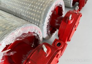
Conveyor pulley welding and machining are the two manufacturing stages that determine whether a pulley runs true, lasts through heavy duty cycles, and transfers torque without fatigue failures. A conveyor pulley is not simply a drum with a shaft; it is a fabricated assembly where the shell, end discs, hub, and shaft are joined by welding and then machined to precise tolerances. In industries such as mining, cement plants, power plant coal handling, and quarry aggregate lines, the quality of these processes directly affects belt tracking, splice life, and bearing performance.
Drive pulleys, tail pulleys, and bend pulleys each place different demands on the weld and the machined surfaces, so the fabrication route should match the pulley’s role rather than treating all pulleys the same.
Welding the Pulley Shell and End Discs
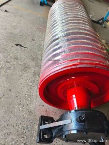
The shell is typically rolled from steel plate and longitudinally welded. End discs are then welded to the shell and to the hub, which is bored to receive the shaft. Weld quality matters because the pulley rotates under continuous bending and torsional loads. Common practice includes:
- Full penetration or deep penetration welds at the hub-to-end-disc joint, where stress concentrates.
- Balanced welding sequences to limit distortion of the shell before machining.
- Preheating and controlled cooling for thicker sections, depending on the steel grade and procedure qualification.
- Dimensional checks after welding to confirm shell roundness and overall length before the machining stage.
On heavy-duty mining conveyor pulleys, the welded assembly may also include wear rings or backing strips that later support rubber lagging. For a tail pulley in a crusher conveyor, the weld design must tolerate impact loads from coarse rock without cracking at the end disc. For a bend pulley in a long overland system, fatigue resistance at the shaft-to-hub connection is the priority.
Machining the Shaft, Hub, and Running Surface
After welding, the pulley is machined to bring the shaft journals, hub bore, end faces, and shell surface into alignment. Typical operations include:
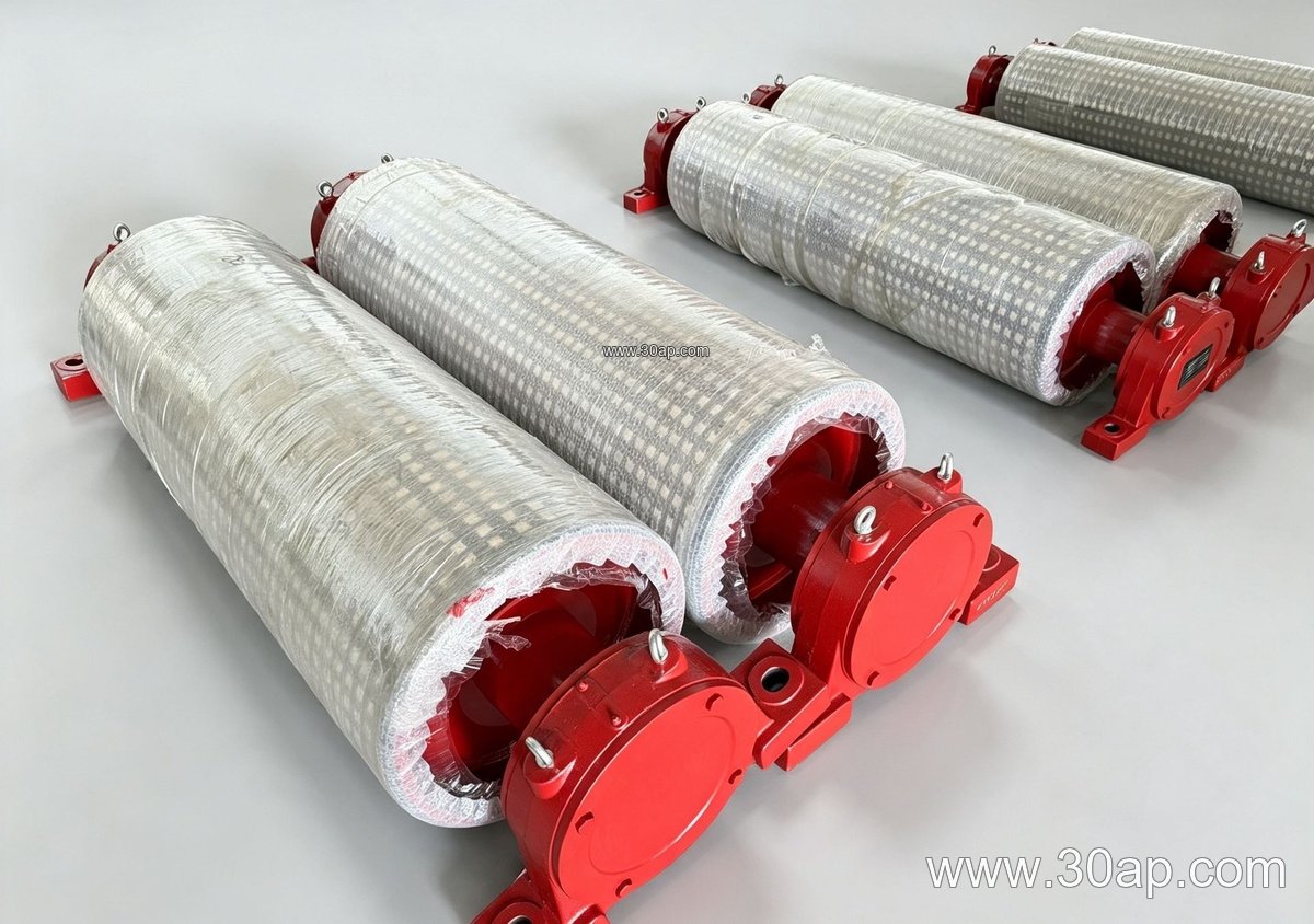
- Turning or grinding the shaft journals to the required bearing fit.
- Boring the hub to match the shaft diameter and keyway.
- Machining the shell outside diameter for concentricity and for lagging adhesion.
- Facing the end discs so the pulley sits squarely on the conveyor bracket.
Concentricity between the shaft axis and the shell surface is critical. Excessive runout causes vibration, uneven belt tension, and accelerated wear on the conveyor belt and on the pulley bearings. In a coal mining conveyor or a cement plant clinker line, even small misalignment can shorten the life of a steel cord conveyor belt or a multi-ply fabric core conveyor belt running over the pulley.
Surface Preparation for Lagging and Belt Contact
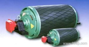
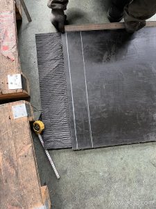
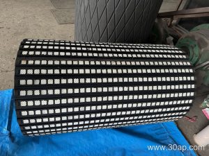
The machined shell surface may remain plain or receive lagging. Common surface forms include plain, rubber lagging applied by cold bonding or hot vulcanizing, diamond grooved lagging, herringbone lagging, and ceramic lagging. Lagging thickness is often 8 mm, 10 mm, 12 mm, 15 mm, or 20 mm depending on the duty. A drive pulley in a wet quarry or a tail pulley in a muddy aggregate line usually benefits from grooved lagging to improve traction and shed material. A bend pulley may use plain or lightly lagged surfaces where only direction change is required.
Machining tolerances for the shell diameter and surface finish affect how well the lagging bonds, especially for hot vulcanized rubber that must cure under pressure against a clean, concentric surface.
How Fabrication Choices Match the Pulley’s Role
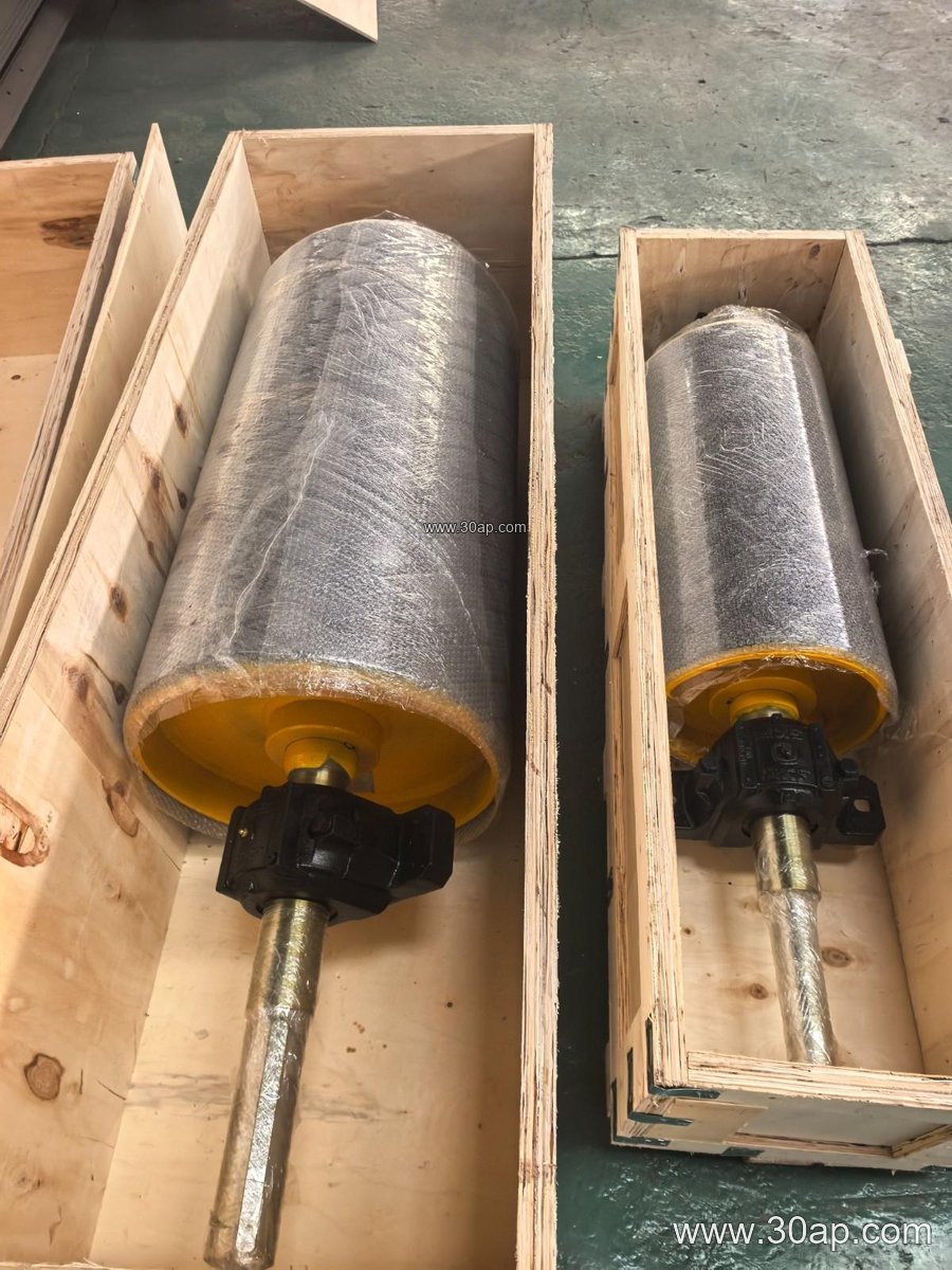
Different pulley types should not be treated as interchangeable. A drive pulley transmits torque and often carries the highest belt tension, so its shaft, hub weld, and lagging receive particular attention. A tail pulley guides the returning belt and may need a self-cleaning or wing design in sticky material. A bend pulley changes belt direction with lower torque but must still run true to avoid edge damage on a 1200mm wide conveyor belt or a 1800mm wide conveyor belt.
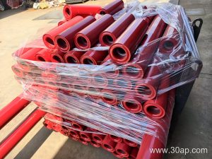
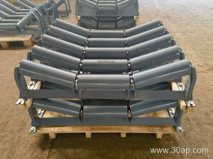
For comparison, a conveyor idler roller is a much lighter rotating component with a different manufacturing route; it does not carry the same welded hub and shaft assembly as a pulley, so its tolerances and materials should not be used as a substitute reference for pulley machining.
Typical Size Ranges and Reference Data
The following values are common reference ranges, not fixed rules. Pulley diameter and shaft size are determined by belt tension, torque, load, and the conveyor design.
| Parameter | Common reference values |
|---|---|
| Belt width (B) | B400, B500, B650, B800, B1000, B1200, B1400, B1600, B1800, B2000, B2200, B2400 |
| Pulley diameter (Ø) | Ø200, Ø250, Ø315, Ø320, Ø400, Ø500, Ø630, Ø800, Ø1000, Ø1250, Ø1400, Ø1600, Ø1800 |
| Shaft diameter (Ø) | Ø50, Ø60, Ø70, Ø80, Ø90, Ø100, Ø120, Ø140, Ø160, Ø180, Ø200 |
| Lagging thickness | 8 mm, 10 mm, 12 mm, 15 mm, 20 mm |
| Example combinations | B800 × Ø500, B1200 × Ø1000, B1400 × Ø800 |
Face width is usually greater than belt width; for example, a B800 belt often runs on a pulley with roughly 950 mm face width, and a B1200 belt on roughly 1400 mm. These are typical proportions, not mandatory matches, and a single belt width can be used with more than one pulley diameter.
What Buyers Should Confirm
When specifying conveyor pulley welding and machining, buyers should ask for the weld procedure and inspection records, the machining tolerances for shaft and shell runout, the lagging type and thickness, and the balancing requirement for the expected belt speed. For a conveyor system handling abrasive ore or heavy bulk material, confirm that the pulley shell thickness and weld details suit the load. Also check that the pulley will fit the conveyor bracket and bearing housing dimensions. Whether the conveyor handles coal, clinker, limestone, or iron ore, the pulley’s welded and machined quality is what keeps the belt running centered and the maintenance intervals predictable.
Related equipment such as the conveyor belt, idler roller, and conveyor bracket should be reviewed together with the pulley specification, because alignment across the whole conveyor frame affects pulley life and belt tracking.