What Pulley Lagging Does
Pulley lagging is the rubber or ceramic layer applied to the shell of a conveyor pulley to improve grip between the drum and the conveyor belt. In a quarry, a coal washing plant, or a power station coal yard, the belt is driven by friction, and a bare steel shell can slip once dust, moisture, or fine slurry gets between the surfaces. The lagging raises the friction coefficient, protects the shell from wear, and helps keep the belt tracking straight under load.
It is not a separate pulley type. The drive pulley, tail pulley, and bend pulley can all carry lagging, but the requirements differ by position, and one should not be treated as a substitute for another.
How the Layer Is Built
Lagging is usually bonded to a prepared shell surface. Common forms include hot-sulfurized rubber, cold-bonded rubber, cast rubber, diamond-grooved rubber, herringbone rubber, plain sheet rubber, and ceramic tile lagging. Thickness is often 8, 10, 12, 15, or 20 mm depending on duty. The bond between rubber and steel matters as much as the rubber itself, because a loose edge can peel under repeated flexing.
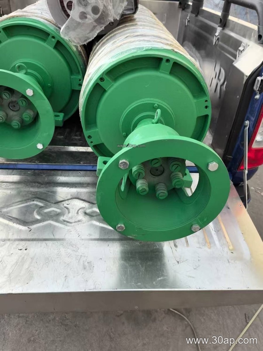
- Plain lagging suits light duty and general conveying.
- Diamond or herringbone grooves help shed water and fines.
- Ceramic lagging is chosen where abrasive material and high slip risk coexist.
Where It Is Used
Drive pulleys at the head of a crushing and screening line benefit most from high-friction lagging, since that is where torque is transmitted. Tail pulleys often use plain or grooved rubber to reduce material build-up, while bend and snub pulleys may need only a thin wear layer. In a cement plant clinker line or an iron ore transfer station, the choice usually follows the material: wet, sticky feed favors grooved surfaces, and sharp abrasive rock favors thicker or ceramic-faced lagging.
Common Size References
The table below shows typical combinations seen in design documents. These are reference values, not fixed rules, and final dimensions follow the conveyor design.
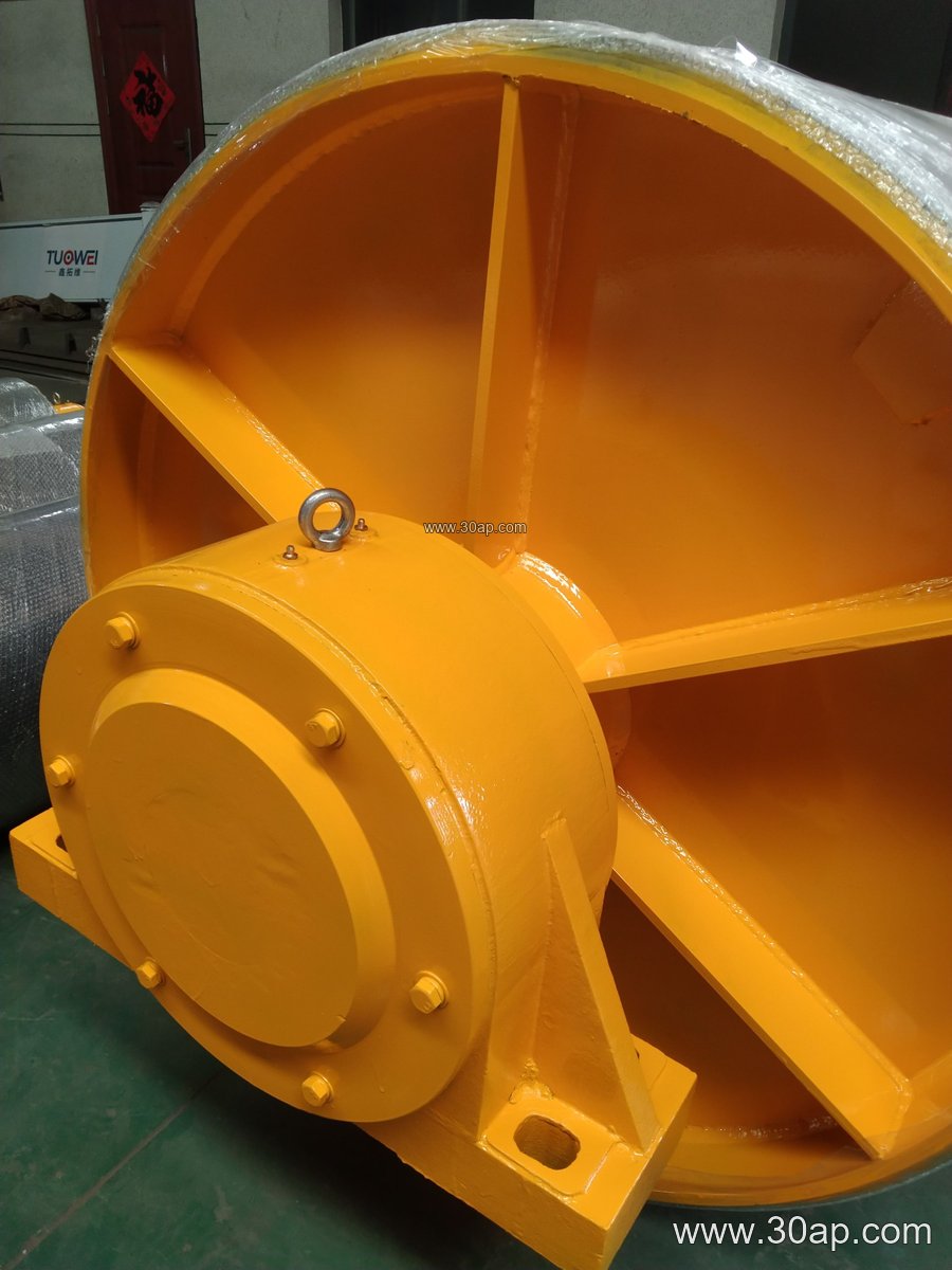
| Belt width | Shell face width (approx.) | Possible pulley diameter | Lagging thickness |
|---|---|---|---|
| B500 | 600 mm | Ø250 to Ø400 | 8 to 10 mm |
| B800 | 950 mm | Ø400 to Ø630 | 10 to 12 mm |
| B1000 | 1150 mm | Ø500 to Ø800 | 12 to 15 mm |
| B1200 | 1400 mm | Ø630 to Ø1000 | 12 to 15 mm |
| B1400 | 1600 mm | Ø800 to Ø1250 | 15 to 20 mm |
| B1600 | 1800 mm | Ø1000 to Ø1400 | 15 to 20 mm |
Shaft diameter is set by torque and load, not by belt width alone. Common shaft sizes run from Ø50 to Ø200 mm, and the engineer should confirm the shaft against the actual drive calculation.
What a Buyer Should Check
First, confirm the pulley position and duty. A drive pulley carrying full motor torque needs a different surface from a bend pulley that only redirects the belt. Second, check the shell face width against the belt width, since the lagging should cover the belt contact area without overhanging. Third, ask about the bonding method and edge treatment, because poorly sealed edges are a common failure point. Fourth, match the surface pattern to the material; grooves that drain water well may pack with sticky fines. Finally, keep spare lagging and a spare pulley assembly on hand for critical circuits, so a worn surface does not stop the whole line.
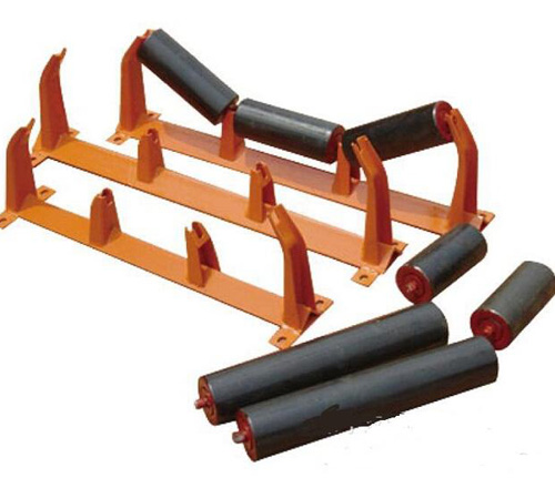
Regular inspection of the lagging, together with the conveyor belt, idler roller, and conveyor bracket condition, keeps the drive efficient and reduces belt slip and misalignment.