What a Conveyor Guide Idler Does
A conveyor guide idler is a specialized roller assembly used to keep the conveyor belt centered and aligned as it travels along the carrying and return sides. Unlike standard carrying idlers that primarily support the belt and material load, the guide idler—often referred to as a self-aligning idler or training idler—applies corrective force when the belt begins to drift sideways. This function is critical in industries such as mining, coal preparation, cement plants, power station coal handling, and aggregate quarries, where mistracking can cause spillage, edge damage, and unplanned downtime.
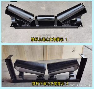
The guide idler works by using angled rollers or a pivoted frame that responds to belt misalignment. When the belt contacts the guide roller, the resulting friction creates a steering effect that nudges the belt back toward the center line. This passive correction reduces the need for manual adjustment and helps protect the conveyor belt, pulleys, and structure from uneven wear.
Construction and Key Components
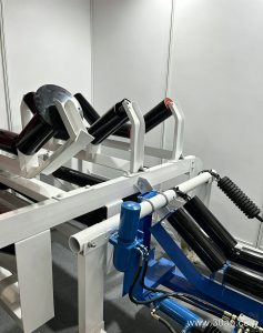
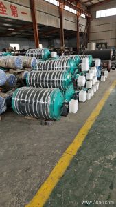
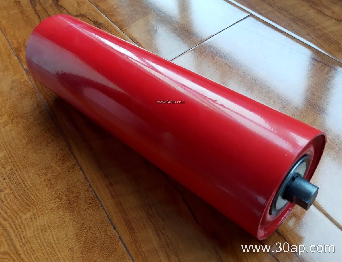
A typical conveyor guide idler consists of a sturdy steel frame, one or more idler rollers, and a mounting arrangement that allows slight rotation or pivoting. The rollers are usually made from steel tube with bearing housings at each end. Common roller diameters include Ø89, Ø108, Ø127, and Ø133 mm, though larger sizes such as Ø159 and Ø178 mm are used on wider or heavier-duty belts. Bearing sizes often follow the roller diameter—6204, 6205, 6305, 6306, and 6308 are frequently specified—but the exact bearing is selected based on load and speed, not solely on roller diameter.
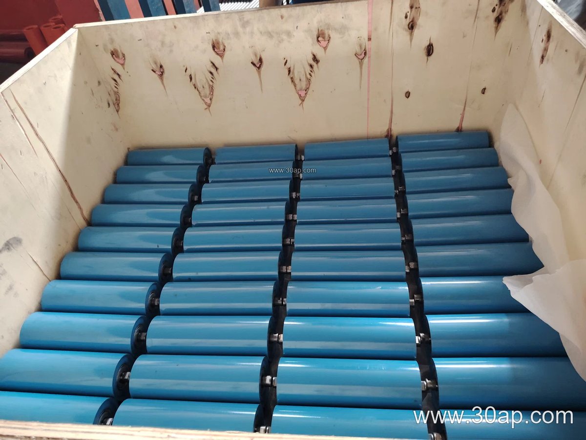
Roller surface options include plain steel, nylon, rubber rings, and ceramic lagging. Rubber or ceramic surfaces can improve grip on the belt edge, which is helpful in wet or dusty conditions. The frame may be fixed or pivoted; pivoted designs are more common for self-aligning guide idlers because they allow the roller to swing and steer the belt.
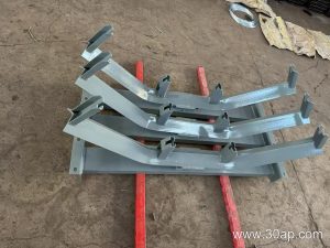
Guide idlers are available in several configurations. A single-roller design is simple and often used on the return side. Two-roller V-type or troughing arrangements provide more contact area and are effective on the carrying side. Three-roller troughing guide idlers combine support and steering, though they are typically heavier and require more space. The choice depends on belt width, material load, and the specific misalignment problem.
Where Guide Idlers Are Used
Guide idlers are installed at points where belt mistracking is most likely: after the discharge pulley, before the tail pulley, on long horizontal runs, and at transitions between inclined and horizontal sections. In a coal handling plant, for example, a guide idler placed just ahead of the transfer chute helps keep the belt centered as it receives material. In a quarry or sand and gravel line, guide idlers on the return side prevent the belt from rubbing against the structure after leaving the head pulley.
They are also used in cement plants, steel mills, fertilizer plants, and grain handling facilities. While the working environment varies, the goal is the same: maintain belt alignment without constant manual intervention. Note that guide idlers are not a substitute for proper conveyor pulley alignment or adequate belt tension. Drive pulleys, tail pulleys, and bend pulleys each have distinct roles, and a guide idler complements—but does not replace—correct system design.
Selection and Sizing Considerations
When selecting a conveyor guide idler, buyers should consider belt width, belt speed, material characteristics, and the available mounting space. Common belt widths range from B400 to B2400, and the idler length must match the belt width and troughing configuration. For a three-roller troughing set, roller lengths often scale with belt width—for example, a B800 belt might use 315 mm rollers, while a B1200 belt might use 465 mm rollers. These are typical examples, not fixed rules; side rollers and center rollers can differ, and the final dimensions should be confirmed with the conveyor design.
Troughing angles of 20°, 30°, 35°, and 45° are common. A 35° troughing angle is widely used in bulk material handling, but the best angle depends on the material’s angle of repose and the belt’s load capacity. For guide idlers, a slight forward tilt of about 1.5° to 2° can enhance self-aligning action, but this should be specified by the conveyor designer.
Bearing selection should consider the load and speed. Common bearing numbers include 6204, 6205, 6305, 6306, 6308, and 6310. Do not assume that a given roller diameter automatically dictates a specific bearing; the bearing must be rated for the actual radial and axial loads.
Mounting brackets and conveyor brackets should be compatible with the existing conveyor structure. Retrofitting a guide idler may require adapter brackets or frame modifications, so check dimensions carefully before ordering.
Maintenance and Troubleshooting
Regular inspection of guide idlers helps prevent unexpected failures. Check for roller rotation, bearing noise, and surface wear. A seized roller can flat-spot the belt or cause mistracking. Lubrication requirements depend on the bearing type; sealed bearings require less frequent attention, but they should still be inspected for seal damage. In dusty environments such as coal or cement plants, keep the idler area clean to prevent material buildup that can interfere with the self-aligning mechanism.
If mistracking persists after installing a guide idler, check belt tension, pulley alignment, and loading conditions. A guide idler can correct minor misalignment, but it cannot compensate for a badly skewed conveyor structure or an overloaded belt. In such cases, consult the conveyor designer rather than adding more guide idlers.
By understanding the role, construction, and selection factors of the conveyor guide idler, maintenance teams and procurement staff can choose the right component for their material handling system and keep the conveyor belt running true.