What a Heavy-Duty Steel Conveyor Bracket Does
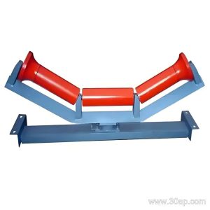
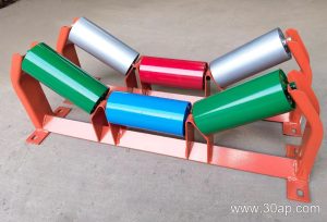
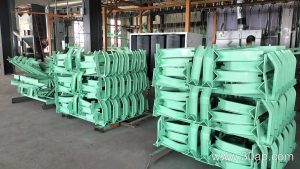
A heavy-duty steel conveyor bracket is the structural support that holds the idler rollers in the correct position under or over the conveyor belt. In a quarry, a coal washing plant, or a cement kiln feed line, the bracket carries the weight of the belt, the material, and the roller itself, then transfers that load into the conveyor frame. The heavy-duty version is made for abrasive, lumpy, or high-tonnage duty where a light stamped bracket would flex, crack, or wear through at the mounting holes.
In everyday plant language this part is also called a heavy-duty conveyor idler bracket or a heavy steel roller support bracket. All three names describe the same item; the subtype still matters, because an upper troughing bracket, a return bracket, and a transition bracket are not interchangeable on the same frame position.
How the Bracket Is Built
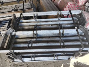
Most heavy-duty steel conveyor brackets are fabricated from angle steel, channel steel, or folded steel plate, then welded or bolted into a rigid assembly. A troughing bracket usually consists of a base beam, two or three roller cradles, and slotted or drilled mounting feet that fix to the conveyor stringer. Thicker section material and gusseted corners are common on heavy-duty designs, and welded seams are usually continuous rather than spot welded.
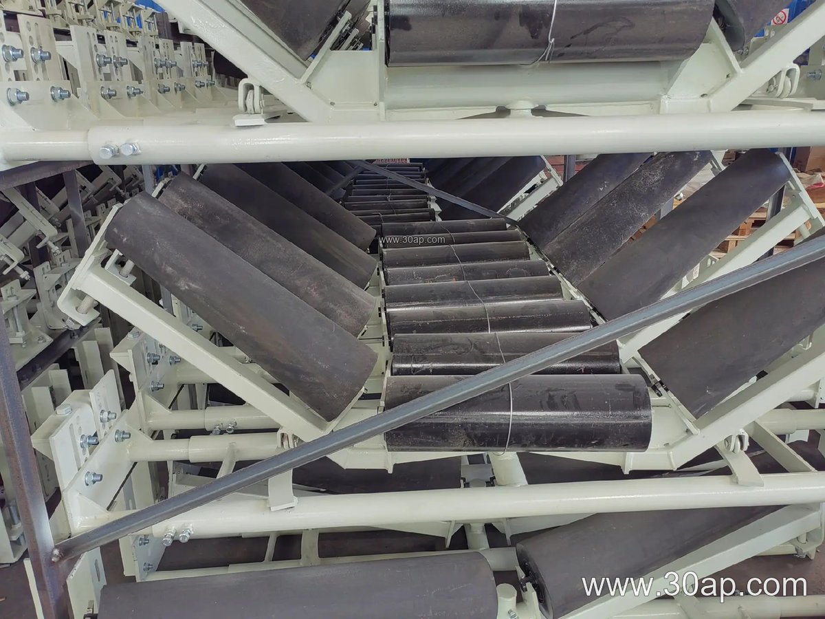
- Angle steel for lighter troughing positions and return supports
- Channel steel for long spans and high-load main frames
- Folded plate for compact, stiff brackets with clean edges
- Bolted or pinned roller seats for easier roller replacement
Surface protection matters as much as the section. Paint, galvanizing, or a protective coating is normally specified for wet coal plants, coastal ports, and wash plants. Buyers should confirm the coating system rather than assume it.
Troughing Angle and Roller Diameter Selection
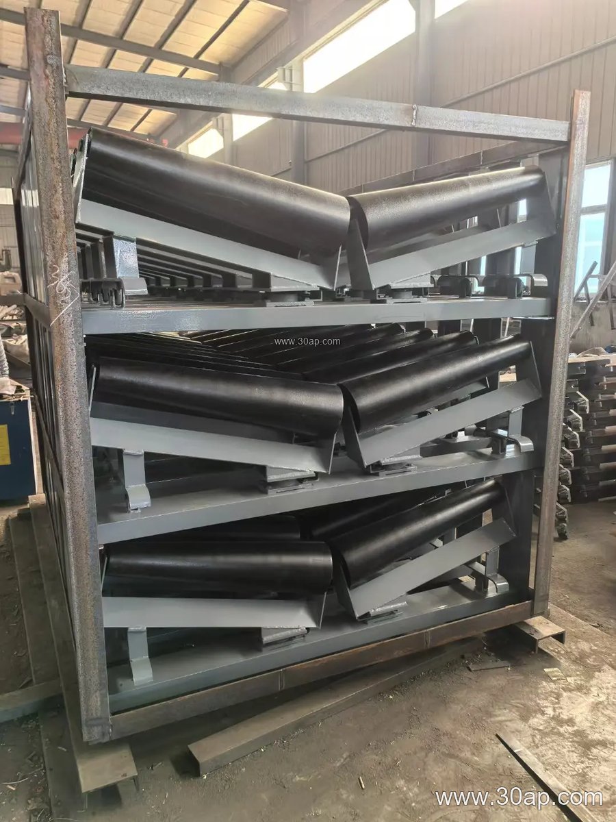
The bracket geometry decides the trough angle and the roller seat spacing. Common trough angles are 20, 30, 35, and 45 degrees. A 20 or 30 degree bracket is often used where the belt is wide and the material is fine, while 35 and 45 degrees suit higher capacity and better material containment. Adjustable brackets allow the same frame to run at several of these angles.
Roller diameter is a separate decision from belt width. Typical idler roller diameters include Ø89, Ø108, Ø133, Ø159, and Ø194, and the bracket cradle must match the chosen roller shaft and end geometry. Belt width and roller diameter are not locked together in a fixed pairing; a B800 frame may be designed around more than one roller size depending on load and belt stiffness. The table below shows common reference combinations, not mandatory matches.
| Reference | Belt width | Trough angle | Typical roller diameter |
|---|---|---|---|
| Light-medium duty | B500 / B650 / B800 | 20° / 30° | Ø89 / Ø108 |
| General bulk duty | B1000 / B1200 / B1400 | 30° / 35° | Ø108 / Ø133 |
| Heavy bulk duty | B1600 / B1800 / B2000 | 35° / 45° | Ø133 / Ø159 / Ø194 |
Mounting hole spacing and crossbeam length change with belt width and trough angle, so these are always determined by design rather than taken as a fixed number.
Where Heavy-Duty Brackets Are Used
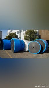
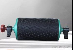
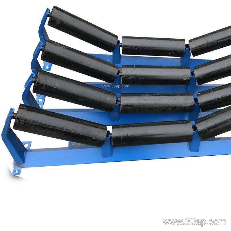
Heavy-duty steel conveyor brackets appear in primary crushing and screening circuits at a limestone mine, in coal handling systems at a power plant, in sintering and pellet plants at a steel works, and in aggregate yards feeding a batching plant. The loading points, impact zones, and long overland runs are where the extra stiffness pays back. In these positions the bracket works together with the conveyor belt, the conveyor pulley at the drive and tail ends, and the idler roller set above or below the belt.
A transition bracket near a pulley is a different subtype from a standard troughing bracket, and a V-return bracket is different again from a flat return bracket. Each has its own place on the frame, so the correct subtype should be ordered for each position.
Buyer Checklist
- Confirm the bracket subtype and mounting position on the frame drawing.
- State belt width, required trough angle, and roller diameter together.
- Ask for the material section and coating system, not just the outline dimensions.
- Check hole spacing and crossbeam length against the existing stringer.
- For adjustable or self-aligning designs, confirm the adjustment range and pivot details.
- Consider spare brackets for impact and transition zones, where wear and distortion are most likely.
Matching the bracket to the actual duty, rather than to a catalogue line alone, keeps the conveyor running straighter and reduces roller and belt wear over the long term.