What a Drive Pulley Does
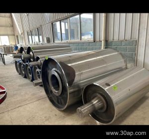
A drive pulley is the powered drum that transmits torque to the conveyor belt, moving material through mines, cement plants, power stations, and aggregate operations. Often called a head pulley when it sits at the discharge end, this component combines structural strength with a surface that grips the belt under load. Unlike a tail pulley or a bend pulley, which guide or tension the belt without driving it, the drive pulley is connected to the gearbox and motor, making it the primary source of motion in the system.
Construction and Key Components
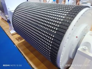
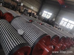
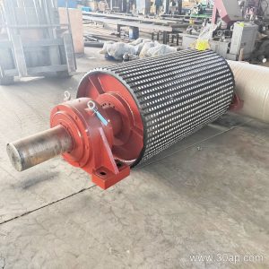
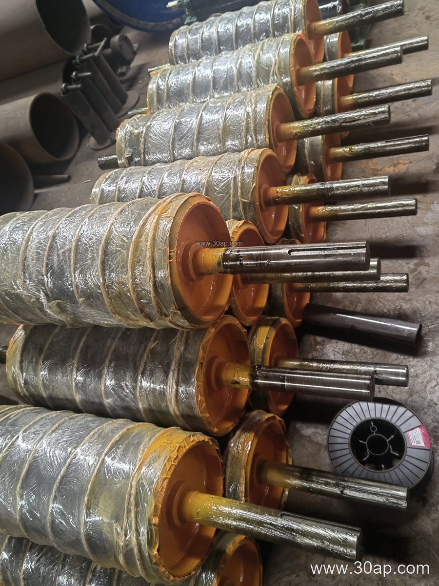
Most drive pulleys are built around a welded steel shell with end discs and a shaft that transfers torque from the drive. The shell diameter and face width are matched to the conveyor belt width and the required belt wrap. Surface options include plain steel, cast rubber, cold-bonded rubber, hot-vulcanized rubber, diamond grooving, herringbone grooving, and ceramic lagging. Lagging thickness commonly ranges from 8 mm to 20 mm, depending on the grip needed and the material being conveyed.
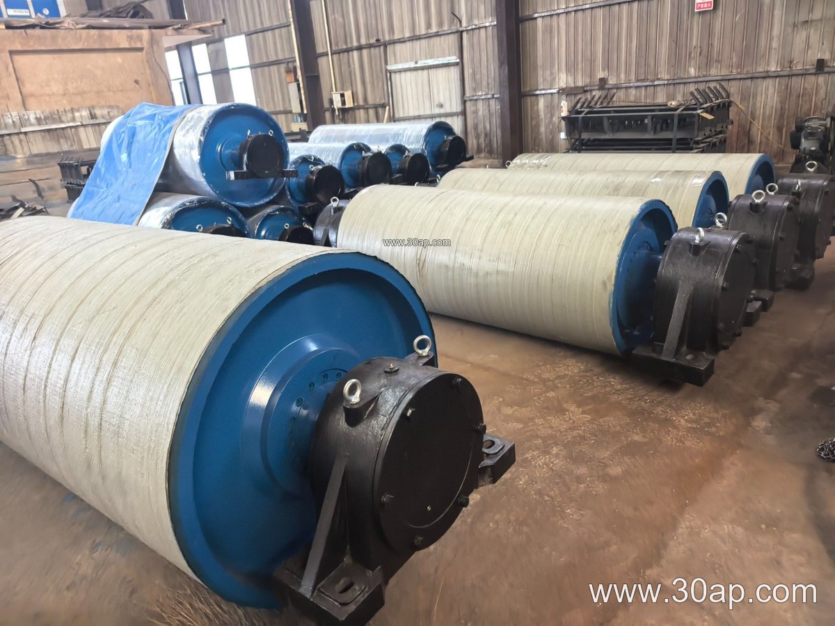
The shaft diameter is determined by torque and load calculations, not simply by belt width. Common shaft sizes include Ø50, Ø60, Ø70, Ø80, Ø90, Ø100, Ø120, Ø140, Ø160, Ø180, and Ø200 mm, but final selection must follow the design engineer’s calculation. Bearing housings, locking assemblies, and keyways are sized to handle the radial and axial forces during start-up and steady operation.
Matching Diameter and Face Width to the Belt
The pulley face width is usually slightly wider than the belt to allow for belt tracking. For example, a B400 belt might use a face width around 500 mm, while a B1200 belt could use approximately 1400 mm. Diameter choices range from Ø200 mm for small conveyors up to Ø1800 mm for heavy-duty applications. A combination such as B800 × Ø500 or B1400 × Ø800 is common in the field, but no single diameter is mandatory for a given belt width. The required wrap angle, belt speed, and tension determine the final geometry.
Typical Reference Combinations (for orientation only)
| Belt Width | Approximate Face Width | Example Diameter Range |
|---|---|---|
| B400 | 500 mm | Ø200–Ø400 |
| B650 | 750 mm | Ø250–Ø500 |
| B800 | 950 mm | Ø315–Ø630 |
| B1000 | 1150 mm | Ø400–Ø800 |
| B1200 | 1400 mm | Ø500–Ø1000 |
| B1400 | 1600 mm | Ø630–Ø1250 |
These values are reference data, not universal specifications. Always confirm with the conveyor designer.
Where Drive Pulleys Are Used
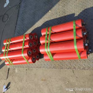
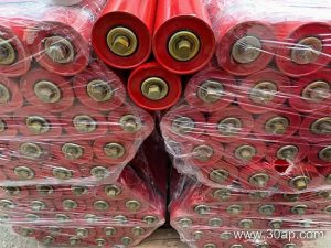
In a limestone quarry, a drive pulley at the head end discharges crushed rock onto a transfer belt. In a coal washing plant, the same component must resist abrasive fines and often uses ceramic lagging for extended grip. Power plants rely on drive pulleys to move coal from stockyard to boiler, while sand and gravel lines use them to handle abrasive aggregate. The drive pulley works alongside conveyor idler rollers, conveyor brackets, and the conveyor belt itself; each part must be compatible to avoid belt mistracking or premature wear.
Buyer Checklist
- Confirm the required torque and belt speed with the conveyor designer.
- Specify the belt width and the corresponding face width, allowing for tracking.
- Choose a lagging type and thickness that match the material and environmental conditions.
- Verify shaft diameter and bearing size based on load calculations, not belt width alone.
- Check that the pulley is balanced for the intended speed and that the surface runout is within acceptable limits.
- Ensure compatibility with the conveyor bracket and idler roller arrangement.
Whether the application is a tunnel mucking conveyor or a fertilizer handling line, the drive pulley remains the critical link between power and material movement. Selecting the right diameter, face width, lagging, and shaft size prevents slip, reduces belt wear, and keeps the conveyor running smoothly.