Why a Large Pulley May Be the Wrong Choice for a Wet Outdoor Conveyor
When specifying a conveyor pulley for a wet outdoor conveyor in a sand and gravel plant, engineers often face a trade-off: a larger diameter reduces belt bending stress and can improve traction, but it also increases weight, cost, and the risk of material buildup on the shell. The common assumption that “bigger is better” deserves a closer look.
How a Conveyor Pulley Works in a Wet Outdoor Conveyor
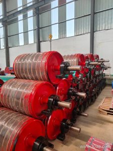
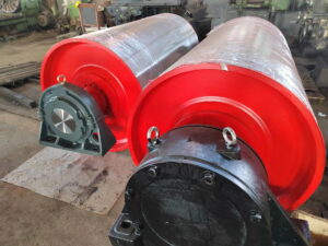
In a sand and gravel plant, the conveyor pulley at the head end drives the belt, while the tail pulley provides tension and tracking. Wet conditions mean the pulley must shed water and prevent slurry from packing between the belt and shell. A conveyor pulley with a self-cleaning lagging pattern and sealed bearings is typically preferred over a smooth drum. The pulley shell, shaft, and hub assembly must resist corrosion and abrasion from grit carried by the belt.
Key Considerations for a Wet Outdoor Conveyor Pulley
- Diameter and face width: A larger pulley reduces belt stress but adds weight and may collect more moisture unless drainage is provided. Match the pulley diameter to the belt thickness and tension rating, not to a rule of thumb.
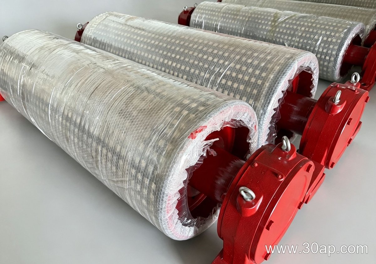
- Lagging: Rubber or ceramic lagging improves grip in wet conditions. Grooved or herringbone patterns channel water away from the contact zone.
- Sealing: Bearing housings must use labyrinth or contact seals to keep out water and fines. A simple felt seal is inadequate for outdoor duty.
- Drainage: Consider a pulley with drain holes or a slight crown to prevent water pooling on the shell.
Practical Example (Hypothetical)
Suppose a sand and gravel plant uses a 500 mm diameter head pulley on a 1,000 mm wide belt. In wet weather, the belt slips because water sits between the lagging and belt. Switching to a 630 mm pulley with grooved rubber lagging and sealed bearings would increase wrap angle and traction, but the larger pulley must be checked for shaft deflection and bearing life. A smaller pulley with improved lagging might solve the slip at lower cost.
FAQ
Can a larger conveyor pulley always improve traction?
No. Traction depends on wrap angle, lagging friction, and belt tension. A larger pulley increases wrap angle but also adds weight and may worsen water retention if drainage is poor.
What is the best lagging for a wet outdoor conveyor pulley?
Rubber lagging with grooves or ceramic tiles is common. The choice depends on abrasion and slip risk, not on a universal recommendation.
How Do You Calculate Conveyor Bracket Spacing and Load for a Mineral Processing Plant?
Conveyor brackets are often selected by eye, but a simple dimension calculation can prevent premature failures. In a mineral processing plant, the bracket spacing and load capacity must be checked against the actual belt and material conditions. This article outlines a hypothetical method with stated assumptions and units.
Step 1: Determine the Load per Bracket
Assume a 1,200 mm wide belt carrying copper ore at 800 t/h. The belt speed is 2.5 m/s and the material bulk density is 2.0 t/m³. First, find the mass per meter of belt: 800 t/h ÷ (2.5 m/s × 3,600 s/h) ≈ 0.089 t/m, or 89 kg/m. Add the belt’s own mass, say 25 kg/m for a heavy-duty belt, giving 114 kg/m. If conveyor brackets are spaced at 1.2 m intervals, the vertical load per bracket is 114 kg/m × 1.2 m = 137 kg. For impact zones, multiply by a dynamic factor of 1.5, yielding 206 kg.
Step 2: Check Bracket Spacing Against Idler Load Limits
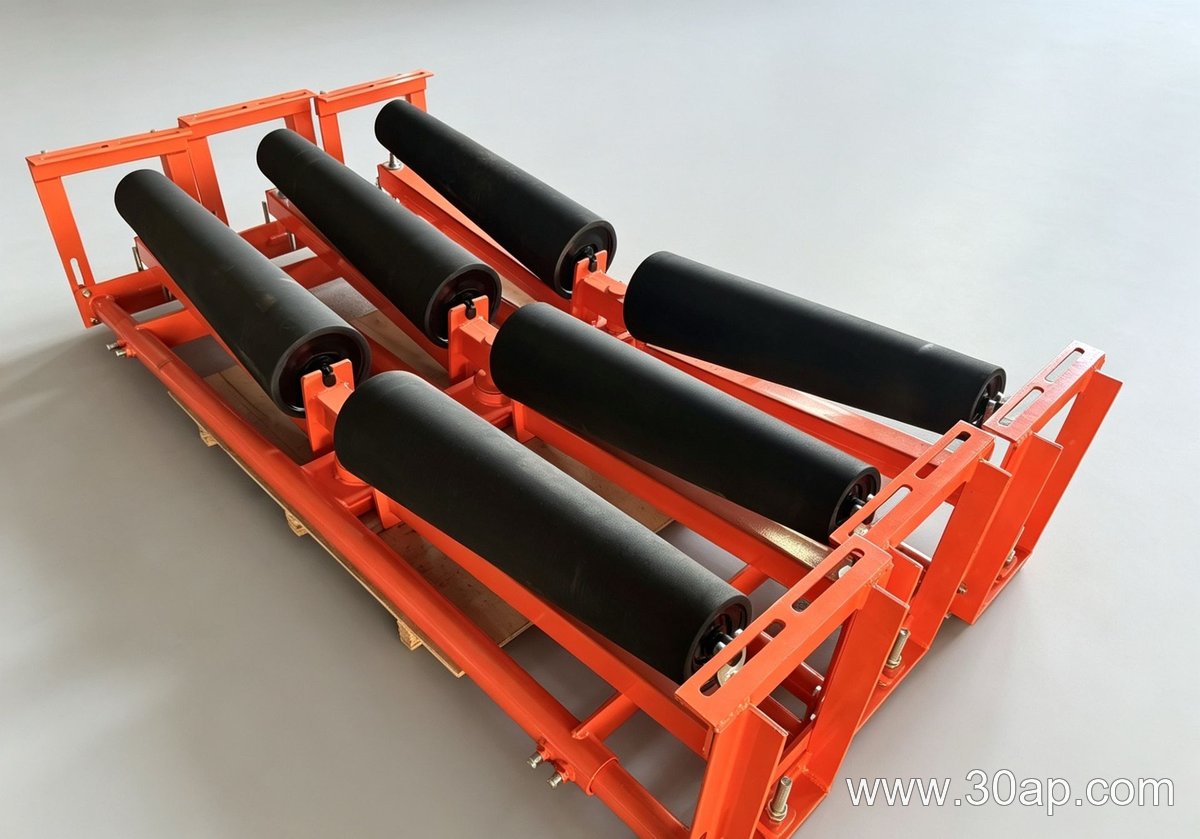
Each conveyor bracket supports one idler roll (or a set). If the idler’s rated load is 250 kg, the static load of 137 kg is acceptable, but the dynamic load of 206 kg leaves little margin. In this hypothetical case, reducing bracket spacing to 1.0 m brings the dynamic load to 171 kg, which is safer. Always verify with the idler manufacturer’s data.
Step 3: Account for Bracket Dimensions and Deflection
Bracket deflection depends on its span and material. For a steel bracket with a 300 mm cantilever, use the formula δ = (F × L³) / (3 × E × I), where F is load in Newtons (206 kg × 9.81 ≈ 2,020 N), L is 0.3 m, E is 200 GPa for steel, and I is the moment of inertia. If I = 50,000 mm⁴ (5 × 10⁻⁸ m⁴), δ ≈ 0.0018 m, or 1.8 mm. That may be acceptable, but a stiffener or thicker section can reduce it.
Practical Notes
- Use consistent units: convert tonnes to kilograms and hours to seconds.
- Dynamic factors vary by material lump size and drop height; 1.5 is a common starting point.
- Bracket spacing also affects belt sag; check against the conveyor’s design sag limit.
These calculations are illustrative only. For a real mineral processing plant, confirm all values with a qualified engineer and the bracket supplier.
Selecting a Conveyor Belt for a 1200 mm Pulley
In a hypothetical mineral processing plant, a new conveyor must transport crushed ore from a secondary crusher to a screening station. The layout fixes the drive pulley diameter at 1200 mm. This dimensional constraint drives the belt selection because the belt must flex around that pulley without exceeding its fatigue limits or slipping. The checklist below guides the choice.
- Confirm the pulley diameter and belt thickness compatibility.
- Determine the maximum lump size and belt width.
- Assess the required tensile strength for the load and incline.
- Select the cover grade for abrasion and impact.
Why Pulley Diameter Dictates Belt Construction
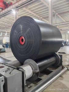
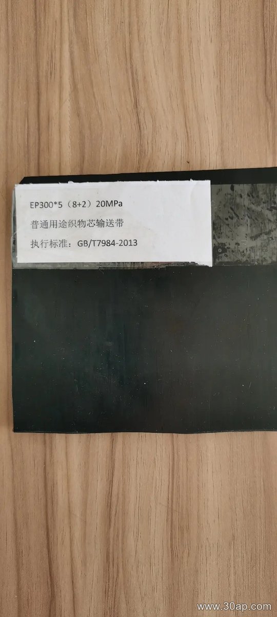
A conveyor belt bends around pulleys. The ratio of pulley diameter to belt thickness affects the strain on the outer carcass. For a 1200 mm pulley, a belt with a total thickness of 15 mm gives a ratio of 80:1, which is generally acceptable for fabric-core belts with multiple plies. Steel-cord belts require larger ratios, often above 100:1, so a 1200 mm pulley may be marginal for heavy steel-cord construction. Therefore, a fabric-core belt with four plies is a practical starting point for this hypothetical project.
Matching Belt Width to the 1200 mm Pulley
The pulley face width must exceed the belt width. If the pulley face is 1400 mm, a belt width of 1200 mm leaves 100 mm on each side for misalignment. The belt must also handle the largest lump. A rule of thumb: belt width should be at least three times the maximum lump dimension. If the crushed ore top size is 300 mm, a 1200 mm wide belt is suitable.
Estimating Tensile Strength
Suppose the conveyor is 150 m long, rises 15 m, and carries 800 t/h of ore with a bulk density of 1.8 t/m³. The belt speed is 2 m/s. The required tension can be calculated from the power needed to overcome friction and lift. A simplified method uses the following formula for effective tension (Te): Te = (L × g × (2 × mi + (2 × mb + mm) × cosθ) × μ) + (H × g × mm). Here, L is length, g is gravity, mi is idler mass per meter, mb is belt mass per meter, mm is material mass per meter, θ is incline angle, μ is friction factor, and H is lift. For this hypothetical case, Te might be around 80 kN. With a safety factor of 10:1, the belt’s rated tensile strength should be at least 800 N/mm. A fabric belt with 4 plies of EP (polyester-nylon) fabric, each rated 200 N/mm, gives 800 N/mm. This matches the requirement.
Cover Grade for Abrasive Ore
Crushed ore is abrasive. A cover grade with good abrasion resistance, such as DIN 22102 grade Y or equivalent, is appropriate. The cover thickness depends on impact energy. For lumps up to 300 mm, a top cover of 6 mm and bottom cover of 2 mm is a common starting point. These values are illustrative and must be verified by the belt supplier.
Final Check: Belt Thickness vs. Pulley
With 4 plies, each about 1.5 mm thick, plus covers, the total belt thickness is roughly 14 mm. The 1200 mm pulley gives a ratio of about 85:1, which is within the acceptable range for fabric belts. If a thicker belt were chosen, the ratio would drop below 80:1, risking premature fatigue. Thus, the 1200 mm pulley constraint effectively limits the belt to a fabric-core construction with no more than four plies.
This parameter-driven approach ensures the conveyor belt fits the mechanical envelope while meeting the duty. Always confirm final selections with the belt manufacturer and a qualified engineer.
Idler Roller Selection for Coal Conveying
At a bulk-material port terminal, coal arrives by rail or ship and is transferred to stockpiles or vessels via conveyor belts. The idler roller—the rotating cylinder that supports the belt—must handle coal’s unique characteristics: it is relatively light but highly abrasive, can be dusty, and may become sticky when wet. Choosing the right idler roller involves balancing load capacity, abrasion resistance, and environmental protection. A common trade-off is between a heavier, more robust roller that costs more upfront and a lighter roller that may wear faster. For coal, the former often pays off in reduced downtime.
Key Considerations for Coal Service
Coal dust is pervasive and can penetrate bearings, causing premature failure. Therefore, an idler roller with effective labyrinth seals or contact seals is essential. Abrasion from coal particles, especially at loading points, demands a thick-walled tube and possibly a sacrificial wear ring. Impact resistance matters at transfer chutes where coal lumps fall onto the belt; impact idlers with rubber discs absorb shock. In addition, coal can be corrosive when wet, so bearing housings should be protected against moisture. For a port terminal, where conveyors run continuously, low rolling resistance also saves energy. However, sealing and low friction often conflict: tighter seals exclude dust but add drag. A practical compromise is a multi-stage labyrinth seal with a grease-filled chamber, which blocks dust while allowing periodic relubrication.
Idler Roller Types for Coal Handling
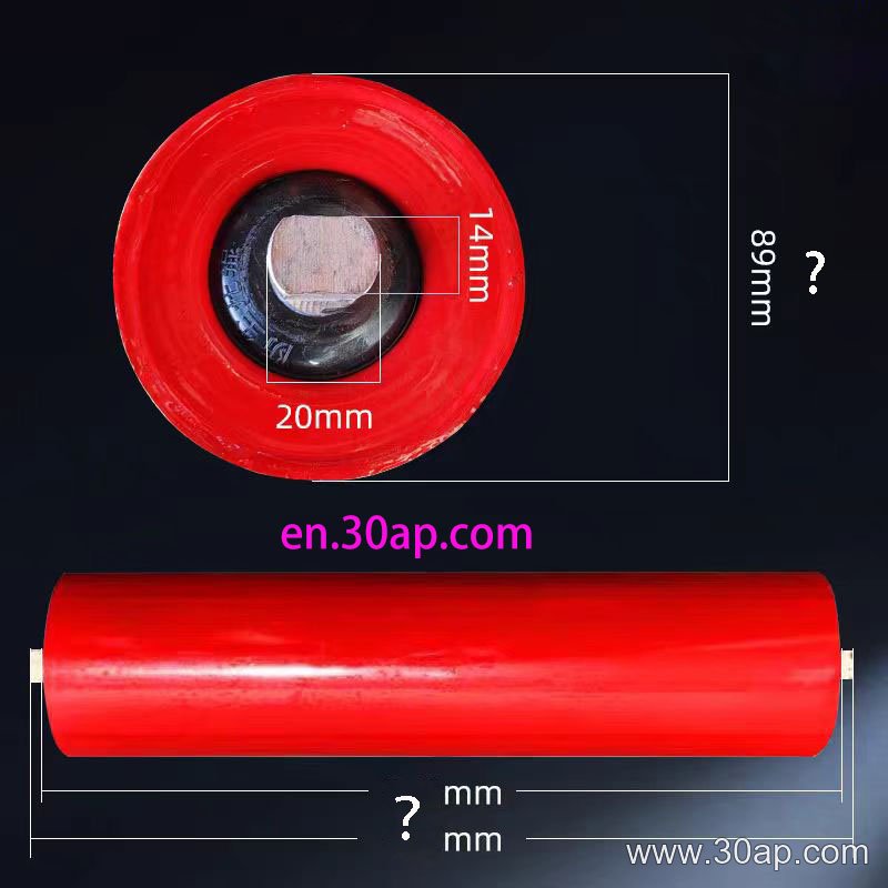
Not all idler rollers suit coal equally. Troughing idlers, typically in a three-roll set, form the belt into a trough to contain the load. For wider belts or higher capacities, a five-roll idler set can reduce belt stress and improve load distribution. At the load zone, impact idlers with resilient discs are preferable to standard rollers. Return idlers, which support the empty belt, can be plain or spiral; spiral rollers shed sticky coal. In a port terminal, a combination of troughing idlers, impact idlers, and return idlers is common. The choice of roll diameter and bearing type depends on belt speed and load, which should be calculated from actual operating data.
Maintenance and Longevity
Even the best idler roller fails eventually. In coal service, regular inspection for seized bearings, worn tubes, and material buildup is vital. A seized roller can wear through the belt quickly. Keeping idlers clean and ensuring proper alignment reduce wear. For port terminals, where salt air may be present, corrosion-resistant coatings or stainless-steel components can extend life. However, these add cost. A maintenance plan that includes lubrication and replacement schedules is more effective than relying solely on premium materials.
Frequently Asked Questions
Q: What is the typical spacing for idler rollers in coal conveyors?
A: Spacing depends on belt tension and load. A common rule is to space carrying idlers so that belt sag between rollers does not exceed 2% of the span. For coal, which is relatively light, spacing can be wider than for heavy ore. However, at loading points, closer spacing is needed to support impact. Always refer to conveyor design standards and calculate based on your specific belt and load.
Q: Can standard idler rollers handle wet coal?
A: Standard rollers may struggle with wet coal because moisture can cause coal to stick to the belt and rollers, leading to buildup and misalignment. In such cases, consider rollers with spiral or rubber-covered surfaces that shed material, and ensure seals are water-resistant. Stainless-steel bearing housings also help resist corrosion.
Q: How do I know when to replace an idler roller?
A: Replace an idler roller when it no longer turns freely, when the tube is worn thin or damaged, or when the bearing is noisy or seized. In coal terminals, a proactive approach is to replace rollers at scheduled intervals based on operating hours, rather than waiting for failure. This prevents belt damage and unplanned downtime.