What the Idler Shaft Does on a Conveyor
In a belt conveyor, the idler shaft is the stationary axle that carries the rotating idler roller. It does not turn with the shell; instead, it holds the roller in position, supports the bearing assemblies, and transfers the load from the belt and material down to the conveyor bracket and frame. Whether the application is a quarry conveyor moving crushed stone, a coal mining conveyor in an underground roadway, or a cement plant feeding clinker to the mill, the shaft is a small but critical link in the load path.
Because the shaft stays fixed while the roller spins, its fit, straightness, and surface finish matter as much as its raw strength. A bent or poorly machined shaft can cause vibration, premature bearing wear, and belt tracking problems that are often blamed on the idler roller itself.
Construction and Common Configurations
Most idler shafts are made from round carbon steel bar, machined at the ends to seat bearings and to accept the mounting slots or flats of the conveyor bracket. Depending on the idler type, the shaft may be through-going or stub-type, and it may carry one roller or several in a multi-roll set.
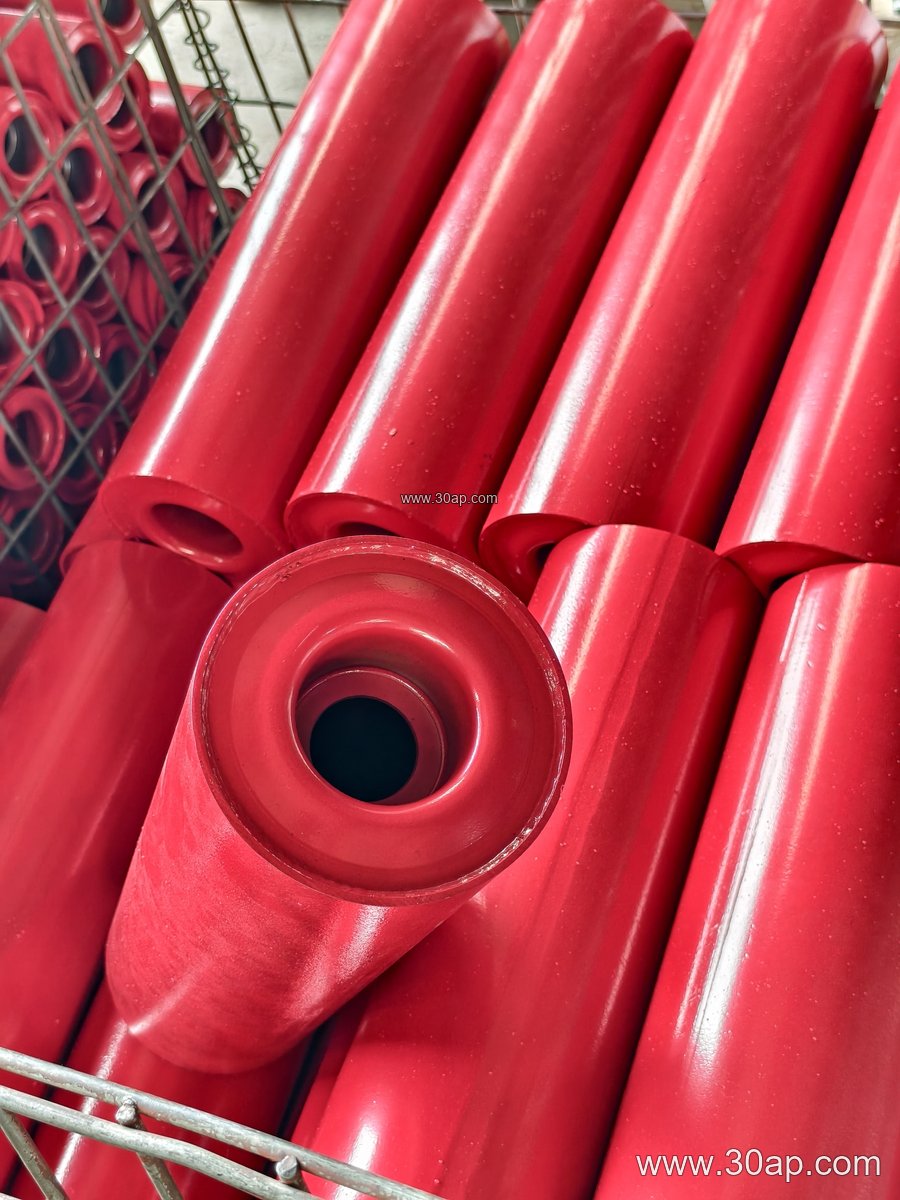
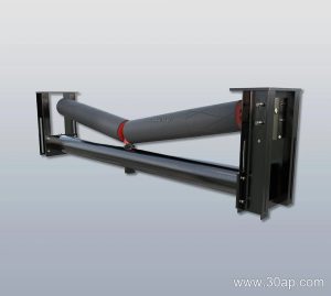
The shaft design follows the idler arrangement. A three-roll troughing set uses a center roller and two side rollers, each with its own shaft or a shared spindle depending on the manufacturer’s design. A V-return set uses two angled rollers, while a single flat return roller uses one shaft across the belt width. Impact idlers with rubber rings, spiral idlers for self-cleaning, and self-aligning idlers all impose different loads and therefore different shaft requirements.
- Troughing and carrying idlers: shafts sized for the belt width and the weight of the material load.
- Return idlers: often simpler shafts, but still must resist bending under belt tension.
- Impact and buffer idlers: shafts may be heavier to absorb shock at transfer points.
- Self-aligning idlers: shaft ends may be shaped to allow slight pivoting for belt training.
Where Idler Shafts Are Used
These components appear wherever a conveyor belt runs on rollers. In a limestone quarry or aggregate line, they carry abrasive rock and dust. In a coal preparation plant or power plant coal yard, they operate in dusty and sometimes wet conditions. In a port handling iron ore or copper ore, they face heavy loads and continuous duty. The same shaft design principles apply across these sites, but the environment guides the choice of bearing protection, shaft coating, and material grade.
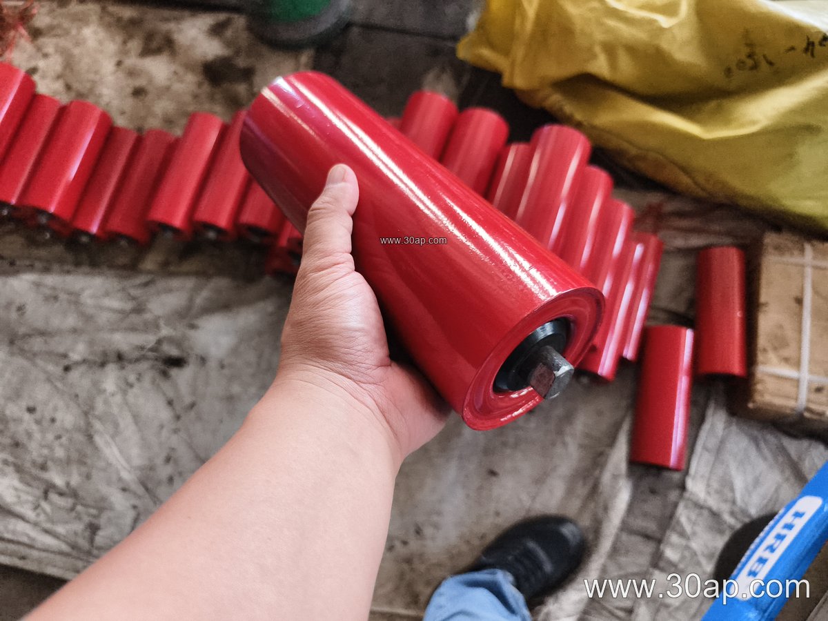
The shaft also interacts with the conveyor belt itself. A misaligned shaft can train the belt poorly, while a shaft with the correct elevation and spacing helps maintain a stable trough. This is why shaft dimensions are usually considered together with roller diameter, belt width, and trough angle rather than in isolation.
Dimensions and Reference Data
Idler shaft sizes are not universal. They are selected according to the idler roller diameter, the belt width, the load, and the bracket design. The table below shows common reference ranges for roller diameters and belt widths that influence shaft selection. These are examples, not fixed rules, and final dimensions should be confirmed with the idler manufacturer.
| Parameter | Common reference values |
|---|---|
| Idler roller diameter | Ø63, Ø76, Ø89, Ø102, Ø108, Ø127, Ø133, Ø159, Ø178, Ø194, Ø219 mm |
| Belt width | B400, B500, B650, B800, B1000, B1200, B1400, B1600, B1800, B2000 mm |
| Trough angle | 20°, 30°, 35°, 45° |
| Bearing series (examples) | 6204, 6205, 6305, 6306, 6308, 6310 |
| Roller length for three-roll troughing (examples) | B500 ≈ 200 mm; B650 ≈ 250 mm; B800 ≈ 315 mm; B1000 ≈ 380 mm; B1200 ≈ 465 mm; B1400 ≈ 530 mm; B1600 ≈ 600 mm; B1800 ≈ 670 mm; B2000 ≈ 750 mm |
Note that side rollers and center rollers can have different lengths within the same troughing set. A shaft that suits a 35° trough set may not suit a 45° set on the same belt width. Similarly, a shaft for a 127 mm roller is not automatically correct for a 159 mm roller, even if the belt width is unchanged.
Buyer Checklist for Idler Shafts
When specifying or replacing idler shafts, buyers should confirm several details beyond the shaft diameter:
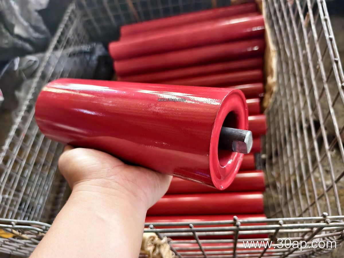
- Idler type and roll configuration: troughing, return, impact, or self-aligning, and whether the set has one, two, or three rolls.
- Roller diameter and belt width: these narrow the shaft and bearing options.
- Bearing number and seal type: the shaft journal must match the bearing bore and the sealing arrangement.
- Mounting details: flat ends, threaded ends, circlip grooves, or bracket-specific features.
- Operating environment: abrasive dust, moisture, or high temperature may call for different shaft protection.
The shaft should be checked for straightness, journal finish, and correct fit before installation. A shaft that is forced into a bracket or bearing can preload the bearing and shorten service life.
Interaction with the Rest of the Conveyor
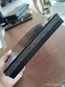
Idler shafts do not work alone. They sit inside idler rollers, which support the conveyor belt, and they are held by conveyor brackets attached to the frame. The belt itself may be a rubber conveyor belt, an EP conveyor belt, or a steel cord conveyor belt, and each has different tension and load characteristics that influence idler and shaft selection. In dusty quarry or mining service, a well-sealed bearing and a straight shaft often do more for reliability than a heavier shaft alone.
For anyone sourcing conveyor components, it helps to treat the idler shaft as part of the complete idler assembly rather than a generic pin. Matching shaft, roller, bearing, and bracket correctly reduces downtime and keeps the belt running true.