What Is a Conveyor Drive Pulley
The conveyor drive pulley, often called the head pulley, is the powered component that transmits motion to the conveyor belt. It grips the belt on its return side and pulls the loaded strand forward. Unlike a tail pulley that merely redirects the belt or a bend pulley that changes its path, the drive pulley is connected to the gearbox and motor, making it the heart of the conveyor’s propulsion system. In industries such as mining, cement plants, power stations, and quarry operations, this pulley must handle continuous heavy loads while maintaining reliable traction.
Construction and Key Components
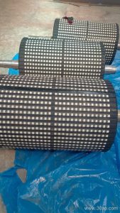
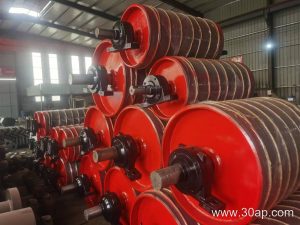
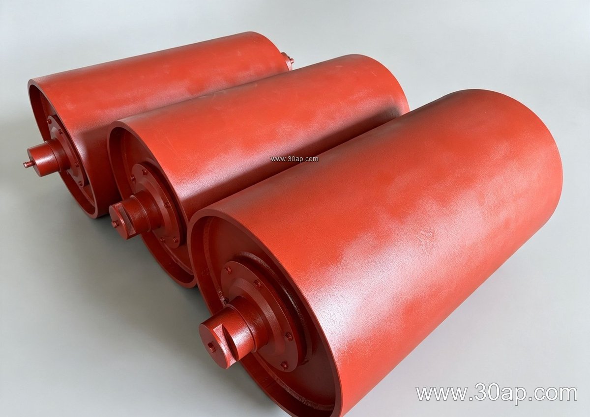
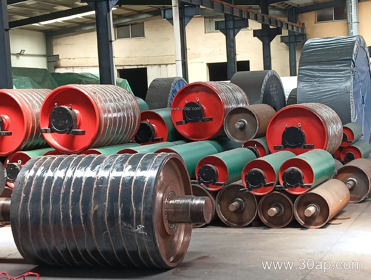
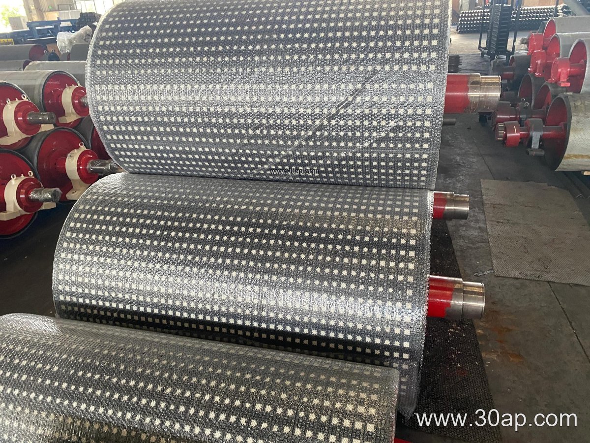
A typical drive pulley consists of a cylindrical shell, end discs, a shaft, and bearing housings. The shell is usually made from rolled steel and may be machined for balance. The shaft is sized according to torque and load, with common diameters ranging from Ø50 to Ø200 mm—never simply matched to belt width. Lagging is applied to the shell surface to increase friction between the pulley and the belt. Common lagging types include plain rubber, cold-bonded rubber, hot-vulcanized rubber, diamond pattern, herringbone, and ceramic lagging, with thicknesses often between 8 mm and 20 mm. The pulley face width is generally wider than the belt; for example, a B800 belt might use a pulley face of about 950 mm, while a B1200 belt could use around 1400 mm.
Where It Is Used
Drive pulleys are found in a wide range of bulk material handling systems. In a coal mining conveyor, they power the main haulage line, often paired with flame retardant conveyor belts and heavy-duty idler rollers. In a limestone quarry, they drive primary crusher feed conveyors, working alongside abrasion resistant conveyor belts. Cement plants use them on clinker conveyors, where heat resistant conveyor belts may be required. Power plants rely on drive pulleys for coal handling systems, and port facilities use them for ship loading operations. Each application places specific demands on the pulley’s design, lagging, and bearing arrangement.
Types and Configurations
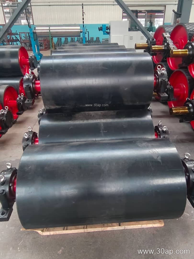
Although the drive pulley is the main subject, it helps to distinguish it from other pulley types. A head pulley is essentially the drive pulley at the discharge end. A tail pulley is located at the loading end and is not powered. A bend pulley changes the belt direction without driving. A take-up pulley maintains belt tension, and a snub pulley increases wrap angle. An electric drum motor integrates the motor inside the pulley shell. For the drive pulley itself, common surface options include smooth, rubber-lagged, and ceramic-lagged versions. The choice depends on the belt type—whether it is a rubber conveyor belt, EP conveyor belt, or steel cord conveyor belt—and on environmental factors like moisture, oil, or heat.
Specifications and Size Selection
Drive pulleys are specified by belt width, pulley diameter, shaft diameter, and lagging type. The table below lists typical reference values; actual sizes are determined by conveyor design, torque, and load conditions. No single belt width dictates a unique pulley diameter, and shaft diameter must be calculated from torque and radial loads.
| Belt Width (mm) | Pulley Face Width (mm) | Common Pulley Diameter (mm) | Common Shaft Diameter (mm) |
|---|---|---|---|
| B400 | 500 | Ø200, Ø250, Ø315 | Ø50, Ø60, Ø70 |
| B500 | 600 | Ø250, Ø315, Ø400 | Ø60, Ø70, Ø80 |
| B650 | 750 | Ø315, Ø400, Ø500 | Ø70, Ø80, Ø90 |
| B800 | 950 | Ø400, Ø500, Ø630 | Ø80, Ø90, Ø100 |
| B1000 | 1150 | Ø500, Ø630, Ø800 | Ø90, Ø100, Ø120 |
| B1200 | 1400 | Ø630, Ø800, Ø1000 | Ø100, Ø120, Ø140 |
| B1400 | 1600 | Ø800, Ø1000, Ø1250 | Ø120, Ø140, Ø160 |
| B1600 | 1800 | Ø1000, Ø1250, Ø1400 | Ø140, Ø160, Ø180 |
| B1800 | 2000 | Ø1250, Ø1400, Ø1600 | Ø160, Ø180, Ø200 |
| B2000 | 2200 | Ø1400, Ø1600, Ø1800 | Ø180, Ø200 |
When selecting a drive pulley, consider the belt’s tension rating, the required wrap angle, and the lagging friction coefficient. For high-tension applications with steel cord conveyor belts, larger diameters and robust shafts are typical. In dusty or wet conditions, ceramic or grooved lagging improves grip. For food or clean environments, smooth or food-grade lagging may be preferred. Always consult the conveyor design manual to match pulley dimensions with the belt’s allowable tension and the system’s power requirements.
Buyer’s Checklist
- Verify belt width and pulley face width; face width should exceed belt width by a suitable margin.
- Confirm pulley diameter based on belt type, speed, and torque—not solely on belt width.
- Specify lagging material and thickness according to environmental conditions (e.g., oil, heat, abrasion).
- Check shaft diameter and bearing selection against calculated loads and torque.
- Ensure compatibility with conveyor brackets and idler rollers for smooth integration.
- Review maintenance access for lagging replacement and bearing lubrication.
In summary, the conveyor drive pulley is a critical investment for any bulk handling system. By understanding its construction, application, and selection criteria, buyers can ensure reliable performance and extended service life. For further assistance on conveyor pulleys, belts, and rollers, please visit our website at www.example.com/conveyor-pulley or contact our technical team.