In a cement plant, a conveyor pulley that stops turning can halt the entire clinker line. Before you choose a replacement, practical answers to a few common questions can save time and prevent repeat failures. Use this quick checklist to frame the conversation: confirm the pulley’s location and duty, check shaft and bearing condition, review lagging wear, and verify that the replacement matches the existing conveyor’s speed and tension requirements.
How do I know whether I need a head pulley or a tail pulley?
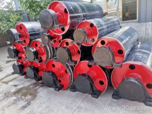
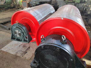
The head pulley is the driven pulley at the discharge end. It transmits power from the drive and often uses lagging to maintain grip. The tail pulley is usually the non-driven pulley at the loading end; it may be a plain wing pulley or a self-cleaning drum. In a cement plant, a head pulley on a clinker belt typically sees higher torque and more abrasive dust, while a tail pulley near the crusher discharge faces impact and material buildup. If you are unsure, trace the belt direction and locate the drive motor—the pulley connected to it is the head pulley.
When should I specify a large conveyor pulley instead of a standard size?
Choose a large conveyor pulley when the belt carries high tension, when you need a longer bending radius for a thick or stiff carcass, or when the available space allows a bigger diameter to reduce belt stress. For example, a hypothetical cement plant moving limestone over a long incline might use a large head pulley to lower the required belt rating and extend splice life. A larger pulley also increases wrap angle and contact area, which can improve traction. However, it adds weight and cost, so confirm that the shaft, bearings and take-up can handle the extra load.
What lagging should I use on a conveyor pulley in a cement plant?
Lagging protects the pulley shell and improves grip. In dry, abrasive cement dust, plain steel may polish and slip. Rubber lagging is common for head pulleys; ceramic lagging can offer better wear resistance in wet or oily conditions. For a tail pulley that tends to build up material, a wing pulley or a self-cleaning drum may be more appropriate than a lagged drum. Always match lagging to the belt and environmental conditions—what works on a clinker belt may not suit a limestone belt with high moisture.
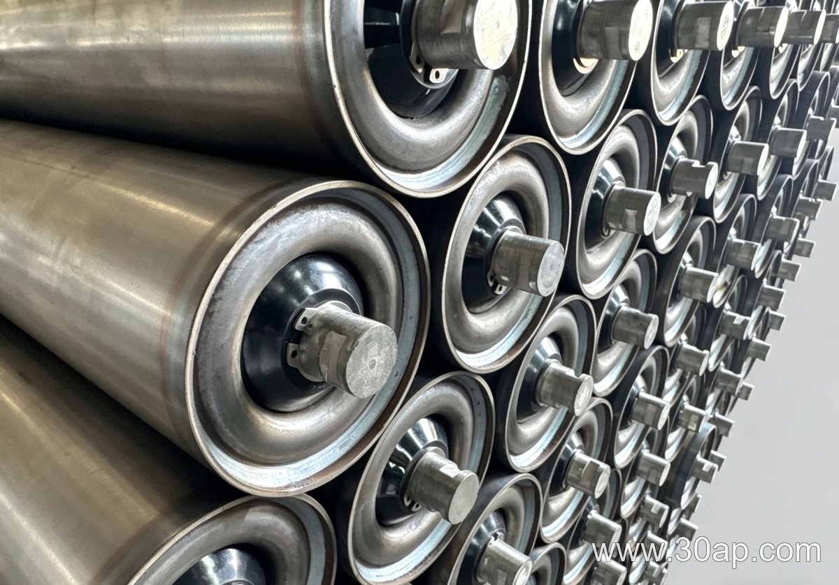
How do I inspect a conveyor pulley before failure?
Look for these warning signs during routine walks:
- Lagging worn thin, glazed or missing in patches.
- Shell cracks, especially near the weld seams.
- Bearing noise, heat or grease leakage.
- Belt tracking problems that persist after adjustment.
- Material buildup on the pulley face or between the belt and pulley.
If any of these appear, schedule a detailed inspection. A pulley that runs hot or wobbles may need immediate replacement to avoid belt damage.
Can I replace a conveyor pulley without changing the belt?
Often yes, but it depends on the pulley diameter and the belt’s take-up range. If the new pulley is larger, you may need to adjust the take-up or shorten the belt. Always verify shaft center distance, keyway dimensions and bearing housings before ordering. In a cement plant, planned shutdown windows are short, so having the correct pulley on site—with the right lagging and shaft—reduces downtime and avoids improvised fixes.
Why a Conveyor Bracket Matters in a Wet Outdoor Aggregate Conveyor
Picture a quarry conveyor that runs year-round, exposed to rain, snowmelt, and washdown spray. The belt carries crushed stone, and every support point must hold its alignment while water drains and grit settles. In this setting, a conveyor bracket is not just a piece of steel—it is the interface between the idler frame and the conveyor structure, and its design determines whether the belt tracks true or wanders off-center after a storm. If the bracket corrodes, flexes, or traps moisture, the whole support system suffers.
Typical Conveyor Bracket Functions in This Application
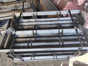
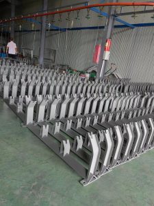
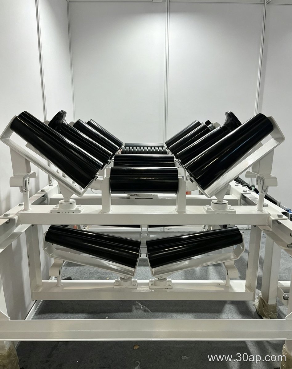
A conveyor bracket in a wet outdoor aggregate plant usually performs several jobs at once. It positions the idler rolls at the correct trough angle, transfers the load from the belt and material into the main stringer, and allows for minor field adjustment. In a trough idler bracket configuration, the bracket also maintains the three-roll trough profile so the belt can carry a deep load without spillage. Because the conveyor is outdoors, the bracket must shed water rather than hold it. Pockets, open seams, and flat horizontal surfaces can collect rain and fine dust, leading to crevice corrosion and eventual section loss.
Key Design and Material Considerations
When specifying a conveyor bracket for this environment, engineers often consider:
- Material grade and coating: hot-dip galvanized steel or a suitable weathering steel may be chosen for wet, mildly corrosive conditions. The exact grade depends on water chemistry and expected service life.
- Drainage geometry: sloped or open profiles help water escape. Avoid cup-like shapes that trap moisture against the belt or frame.
- Fastener compatibility: bolts and nuts should match the bracket material or be isolated to reduce galvanic corrosion.
- Stiffness and load path: the bracket must resist the belt pull and material load without permanent deformation. A hypothetical example might use a 6 mm thick bracket for a 1200 mm wide conveyor, but actual values require engineering calculation.
- Adjustability: slotted holes or shim points can help correct belt tracking after the structure settles.
Installation and Maintenance Notes for Wet Service
During installation, ensure the conveyor bracket sits flush against the stringer and that bolts are torqued to the project specification. After the first few weeks of operation, recheck alignment, because moisture and vibration can loosen connections. In wet service, inspect brackets at least quarterly for rust staining, coating breakdown, and standing water. If a bracket shows pitting or section loss, replace it rather than attempting a field weld unless the repair is engineered. A well-chosen conveyor bracket, matched to the drainage and load conditions, helps keep the conveyor running straight through the wettest months.
Designing a Heavy-Duty Conveyor Belt for a Hypothetical Quarry
This engineering example walks through a hypothetical conveyor belt project for a dusty quarry. The goal is to illustrate how assumptions drive decisions when specifying a heavy-duty conveyor belt. No real customer data is used.
Step 1: Define the Duty and Assumptions
Assume a quarry face produces crushed granite at up to 800 t/h. The conveyor belt must transport material 120 m on a 15° incline. Ambient temperature ranges from -5°C to 40°C. The material contains fines and occasional lumps up to 300 mm. Dust is pervasive.
Key assumptions:
- Belt speed: 2.5 m/s (typical for aggregate, but confirm with pulley and idler limits).
- Material bulk density: 1.6 t/m³.
- Loading point: impact from 2 m drop height.
- Operating hours: 16 h/day, 6 days/week.
Step 2: Select the Conveyor Belt Construction
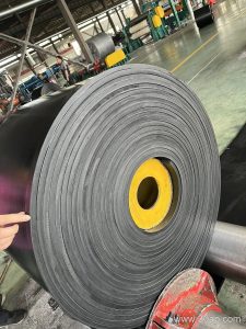
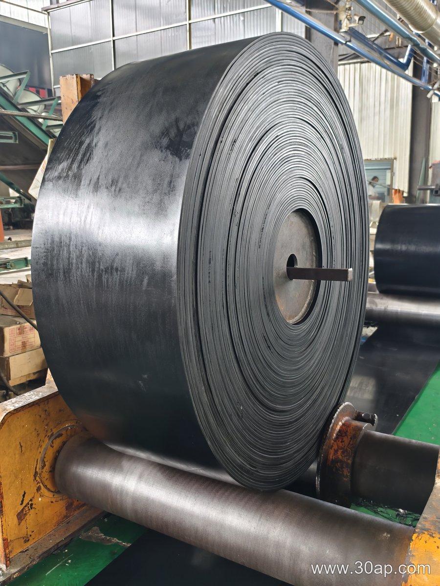
The conveyor belt carcass must handle tension and impact. For this duty, a heavy-duty conveyor belt with a steel cord or fabric carcass is common. Steel cord offers high strength and low elongation, but fabric (e.g., EP) is more tolerant of impact and easier to splice. Given the 120 m length and 800 t/h, a 4-ply EP 630/4 belt with 8 mm top cover and 3 mm bottom cover might be a starting point. Cover compound should be abrasion-resistant (e.g., DIN Y or equivalent) and anti-static for dust.
Why not a food-grade conveyor belt? It is unnecessary here and would add cost without benefit. The dusty quarry demands abrasion resistance, not hygiene.
Step 3: Address Dust and Impact
Dust accelerates wear on the conveyor belt and idlers. Actions:
- Install skirt rubber and dust curtains at transfer points.
- Use a belt cleaner (primary and secondary) to remove fines.
- Choose impact idlers or a impact bed at the loading zone to protect the conveyor belt from lumps.
Cover thickness at the loading zone could be increased to 10 mm, but verify that the belt can still trough properly.
Step 4: Check Tension and Splice
Calculate effective tension using standard methods. Assume friction factor 0.02, lift 31 m, and material load. The resulting maximum tension should be less than the belt’s allowable working tension. For a 4-ply EP 630 belt, working tension is roughly 63 N/mm per ply? (Hypothetical values; always verify with manufacturer.) Splice choice: vulcanized splice for maximum strength, especially for heavy-duty conveyor belt.
Step 5: Review and Iterate
This hypothetical design is not final. It shows how assumptions about material, speed, and environment shape the conveyor belt specification. In a real project, testing and supplier data would refine the choice.
Idler Roller Selection for a Hypothetical Modular Assembly Line
Consider a hypothetical modular assembly line that moves totes weighing up to 25 kg at 0.5 m/s. The conveyor has a 4 m straight section followed by a 90-degree curve. The project team must choose an idler roller that balances cost, maintenance, and belt tracking. Below is a compact checklist of assumptions and decisions for this engineering example.
- Belt width: 400 mm
- Roller diameter: 50 mm
- Roller spacing: 150 mm
- Environment: indoor, clean, 20°C
- Duty: 8 hours/day, 5 days/week
Step 1: Define the Load per Idler Roller
Assuming the totes are evenly distributed, each idler roller supports a share of the belt and load. With 150 mm spacing over a 4 m section, there are about 26 rollers. The total load (belt + totes) might be roughly 300 kg, so each idler roller carries about 12 kg. This is a hypothetical value; actual loads depend on belt weight and dynamic factors. The key decision: choose a roller with a static load rating well above 12 kg to account for shock and misalignment.
Step 2: Choose the Bearing and Seal for the Environment
In a clean indoor setting, a standard deep-groove ball bearing with a contact seal is sufficient. For wet or dusty conditions, a labyrinth seal or polymer bearing might be better. Here, the team selects a 6204 bearing with a nitrile seal. The idler roller must have a shaft that fits the bearing bore with a light press fit to prevent rotation of the inner ring.
Step 3: Decide on Roller Material and Surface
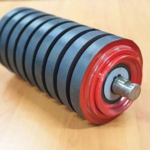
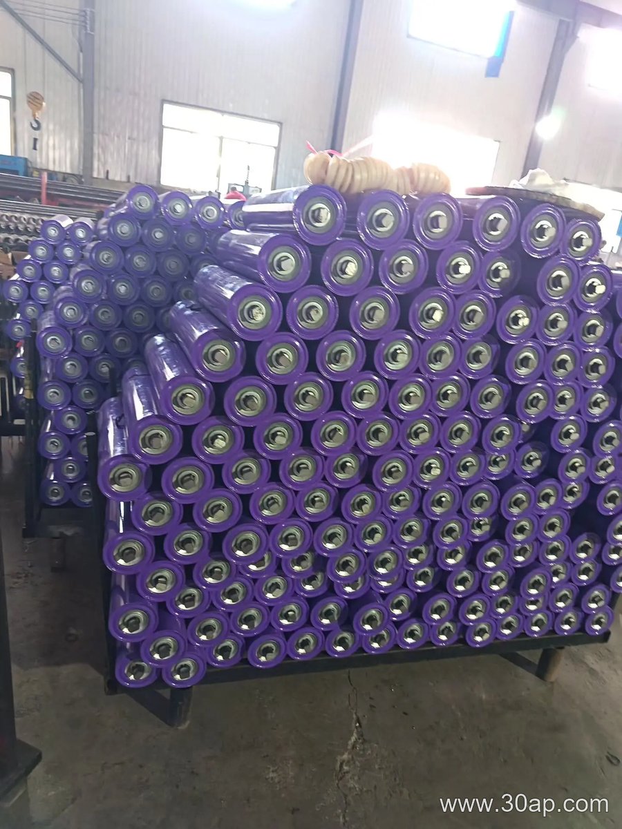
Steel rollers are durable but can be noisy. Polymer rollers reduce noise and resist corrosion. For this line, the team chooses a galvanized steel idler roller. Galvanizing provides moderate corrosion resistance at lower cost than stainless steel. The roller surface should be smooth and true; excessive runout causes belt vibration. A target total indicator reading (TIR) of 0.5 mm is reasonable for this speed.
Step 4: Address Belt Tracking at the Curve
The 90-degree curve requires a belt tracking idler roller with a slight crown or guide rollers. A crowned idler roller helps center the belt by creating a restoring force. The team specifies a 1 mm crown over the 400 mm face. Alternatively, vertical guide rollers on the sides can be used. The decision depends on belt type and tension; a crowned idler roller is simpler but may not suit all belts.
Step 5: Verify Maintenance and Replacement
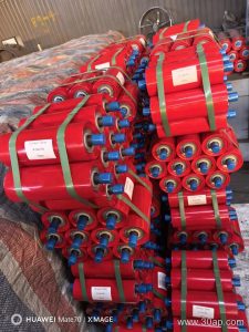
Idler rollers should be easy to replace. The team chooses a roller with a spring-loaded shaft or hexagonal shaft that fits into a bracket. This allows quick removal without tools. Spare idler rollers should be kept on hand; a failed roller can stop the line. The hypothetical project assumes a 2-year replacement interval based on 4,000 operating hours.
This example shows that idler roller selection involves load, bearing, material, and tracking decisions. Each choice affects the others. By stating assumptions and calculating loads, engineers can specify an idler roller that performs reliably without over-engineering.