What an Idler Bracket Does on a Conveyor
An idler bracket is the supporting frame that holds conveyor idlers in the correct position under or above the belt. It carries the load of the belt and material, sets the trough angle of the carrying idlers, and keeps roller spacing consistent along the line. In a coal handling system, a quarry transfer point, or a cement plant clinker line, this small structural part largely determines whether the belt tracks straight and whether the idlers wear evenly.
Also called a conveyor bracket or idler frame, the part is usually a welded or bolted assembly rather than a single piece. It works together with the conveyor pulley at the drive and tail ends, but it is not a substitute for a pulley and should not be confused with one.
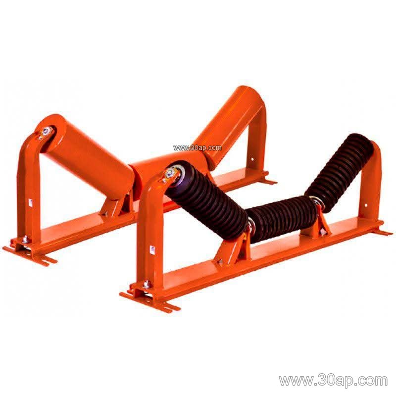
Construction and Common Forms
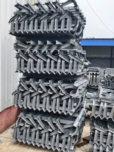
Most brackets are fabricated from angle steel, channel steel, or folded steel plate. The crossbeam length and mounting hole spacing follow the belt width and trough angle, so they are set by design rather than by a single fixed figure. Common configurations include:
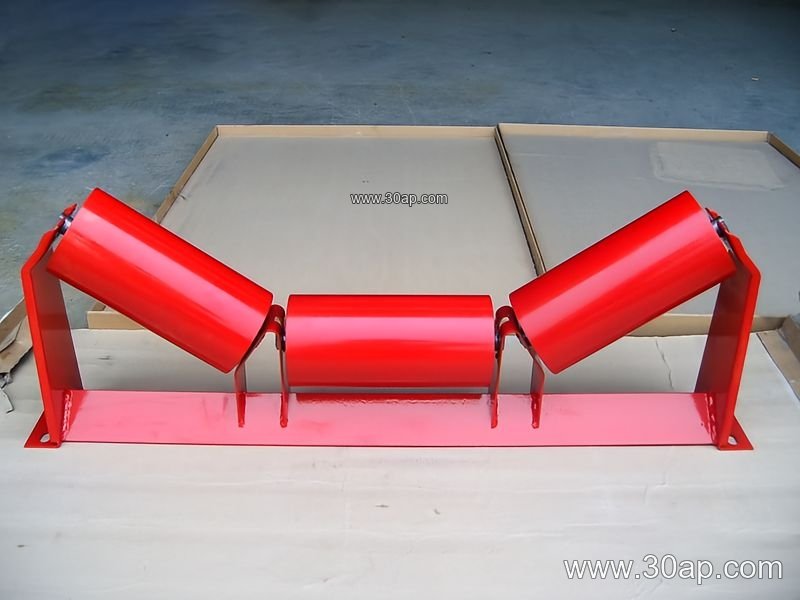
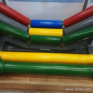
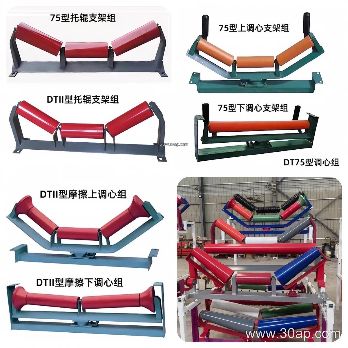
- Troughing brackets for the carrying side, normally arranged in three or five rolls
- Transition brackets near pulleys, where the belt gradually changes shape
- Return brackets and V-return brackets for the empty strand
- Impact brackets at loading points, often paired with impact idlers
- Self-aligning and forward-leaning brackets for belt tracking
- Adjustable brackets that allow the trough angle to be changed on site
A typical combination might be written as B800, 35 degrees, with Ø108 idlers, or B1200, 45 degrees, with Ø133 rollers. These are common reference combinations, not mandatory matches; the same belt width can be paired with different trough angles and roller diameters depending on load and belt stiffness.
Where the Bracket Fits in the Line
In a limestone mine or a crushing and screening plant, troughing brackets dominate the carrying run, while return brackets support the belt on its way back. At a transfer chute, impact brackets absorb the drop energy together with cushion idlers. On a long overland line feeding a power plant coal yard, self-aligning brackets help correct minor misalignment before it becomes edge damage. The bracket is always part of a system: the conveyor belt, the idler roller, and the frame must be compatible in width, hole pattern, and height.
Matching Brackets to Belt and Roller
Buyers should confirm the belt width, the required trough angle, the idler diameter, and the mounting hole pattern before ordering. A bracket designed for a 20-degree trough will not position 45-degree idlers correctly, and a frame built for Ø89 rollers may not accept Ø159 rollers without changes. The table below shows common reference values, not fixed supply commitments.
Reference Data for Selection
| Item | Common Options |
|---|---|
| Belt width | B500, B650, B800, B1000, B1200, B1400, B1600, B1800, B2000 |
| Trough angle | 20, 30, 35, 45 degrees; adjustable brackets cover a range |
| Idler diameter | Ø89, Ø108, Ø133, Ø159, Ø194 |
| Material | Angle steel, channel steel, folded steel plate |
| Forward lean | About 1.5 to 2 degrees on forward-leaning types |
For heavy-duty duty such as an iron ore or copper ore line, thicker frames and reinforced welds are usually specified. Where a steel cord conveyor belt or a high-strength EP conveyor belt runs at speed, bracket rigidity matters because flexing frames disturb idler alignment.
Installation and Maintenance Notes
Set brackets square to the belt centerline and at equal spacing along the run. Check that all idlers sit fully in their slots and that the trough angle is the same on both sides. On adjustable brackets, lock the setting after alignment. Inspect welds and bolt connections during scheduled stops, especially at impact and transition zones where vibration is highest. Replacing a bent bracket early is cheaper than replacing the idlers and belt edge it damages.
Whether the plant handles coal, clinker, sand, or grain, the idler bracket remains a low-cost part with a large influence on belt life. Confirm dimensions against the actual frame and roller drawing, and treat published sizes as a starting point for the selection discussion.