What a Conveyor Frame Does on a Belt Conveyor
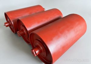
A conveyor frame is the structural backbone that holds the idler roller sets, conveyor pulley assemblies, and conveyor bracket connections in alignment along the belt path. In a quarry, a coal washing plant, or a cement clinker line, the frame carries the weight of the conveyor belt, the material load, and the dynamic forces from starting and stopping. Without a rigid, well-aligned frame, the belt drifts, the idlers wear unevenly, and the whole conveyor line loses efficiency.
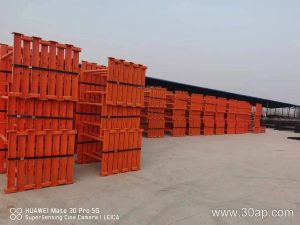
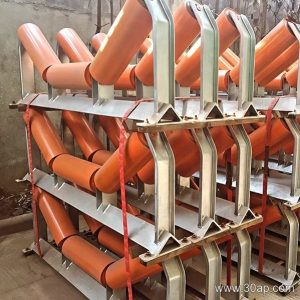
The frame is not a single part. It is a system of longitudinal beams, cross members, support legs, and mounting points that together define the belt line. Engineers often call the complete assembly the conveyor support structure, and the individual sections are fabricated from angle steel, channel steel, or folded steel plate.
How the Frame Is Built
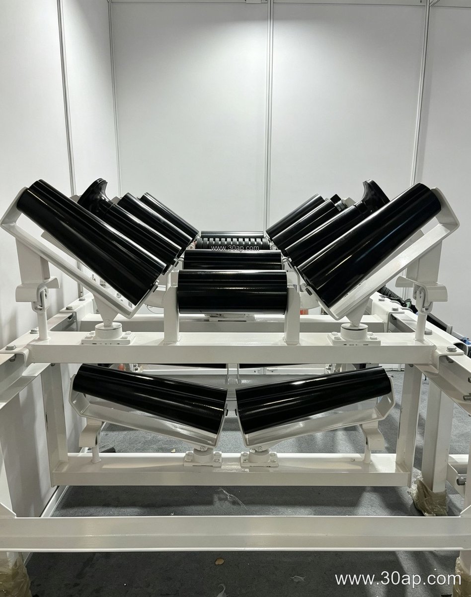
Most frames are modular. Each section includes two side rails connected by cross beams, with mounting holes drilled for the idler brackets. The cross beam length and hole spacing change with belt width and trough angle, so they are determined by design rather than fixed across all conveyors.
Common fabrication materials include:
- Angle steel for lighter duty sections and walkway supports
- Channel steel for main longitudinal rails on heavier lines
- Folded steel plate for compact cross members and transition zones
Welded or bolted construction is selected according to transport and installation conditions. Bolted frames are easier to ship to remote sites such as tunnel mucking projects or limestone mines, while welded frames offer higher stiffness where vibration is severe.
Frame Types and Their Mounting Positions
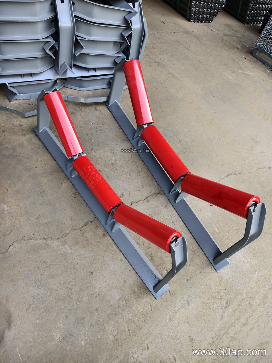
Different frame sections serve different points along the belt. Troughing idler frames support the carrying side and set the trough angle. Return frames hold the belt on the return run, and V-return frames help center the belt. Transition frames guide the belt from the flat pulley area into the trough section. Impact frames, often fitted with buffer idlers, sit under the loading point. Self-aligning frames and forward-tilted frames assist belt tracking on long runs.
Adjustable frames allow the trough angle to be changed between common settings such as 20, 30, 35, and 45 degrees. This flexibility is useful during commissioning or when material characteristics change. Fixed frames, by contrast, lock the geometry and are chosen when the belt line is well defined.
Matching Frame Geometry to Belt and Idler Size
Frame selection starts with belt width and idler diameter. Typical belt widths run from B500 through B2200, and idler diameters commonly include Ø89, Ø108, Ø133, Ø159, and Ø194. A frame for a B800 belt at 35 degrees with Ø108 idlers is a common combination in sand and gravel lines, while a B1200 frame at 45 degrees with Ø133 idlers may suit a primary crushing discharge. These are examples, not fixed rules. One belt width can accept more than one trough angle or roller diameter, depending on load and belt speed.
| Frame Section | Common Belt Width Range | Typical Trough Angle | Typical Idler Diameter |
|---|---|---|---|
| Troughing frame | B500 to B2200 | 20 to 45 degrees | Ø89 to Ø194 |
| Transition frame | B650 to B1800 | 20 to 35 degrees | Ø89 to Ø159 |
| Return frame | B500 to B2000 | Flat or V-return | Ø89 to Ø159 |
| Impact frame | B800 to B1800 | 30 to 45 degrees | Ø108 to Ø194 |
| Adjustable frame | B500 to B1400 | 20 to 45 degrees | Ø89 to Ø133 |
Forward-tilted frames usually set the idlers at about 1.5 to 2 degrees to improve tracking. The frame must provide the correct mounting angle without stressing the idler shaft.
Where Conveyor Frames Are Used
These structures appear wherever bulk material moves continuously. In a power plant coal yard, frames support the belt through transfer towers and bunker feed points. In an iron ore beneficiation plant, heavy-duty channel frames carry high-tonnage belts. Aggregate operations, fertilizer plants, and grain silos also rely on properly aligned frames to keep the conveyor belt centered and the idler rollers turning freely.
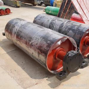
The frame also interfaces with the conveyor pulley at the head and tail. Drive, tail, and bend pulleys each have separate support requirements, and the frame must leave clearance for pulley withdrawal and belt splicing.
What Buyers Should Check Before Ordering
- Confirm belt width and the required trough angle for each section.
- State the idler diameter so bracket heights match the frame.
- Ask for cross beam length and hole spacing as designed for the project, not assumed values.
- Confirm whether the frame is fixed or adjustable, and whether forward tilt is required.
- Check surface treatment and whether the site needs hot-dip galvanizing or paint.
- Review the connection details to the conveyor bracket and support legs.
Accurate frame drawings reduce installation time and help avoid belt misalignment during the first run. Buyers who provide belt width, idler size, trough angle, and loading conditions will receive a frame that fits the conveyor line rather than a generic section.