What a Metallurgical Conveyor Pulley Does
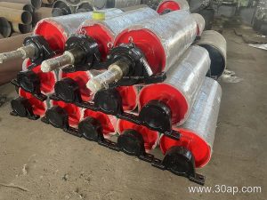
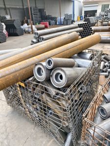
A metallurgical conveyor pulley is the rotating drum that transfers motion to the conveyor belt and holds its path steady under heavy bulk loads. In a sintering plant, a copper concentrator, or a limestone crushing circuit, the belt may carry hot, abrasive, or wet material, so the drum has to combine structural strength with a surface that grips without polishing the belt cover. The same component is often called a conveyor drum or belt pulley, and those equivalent names describe the same product.
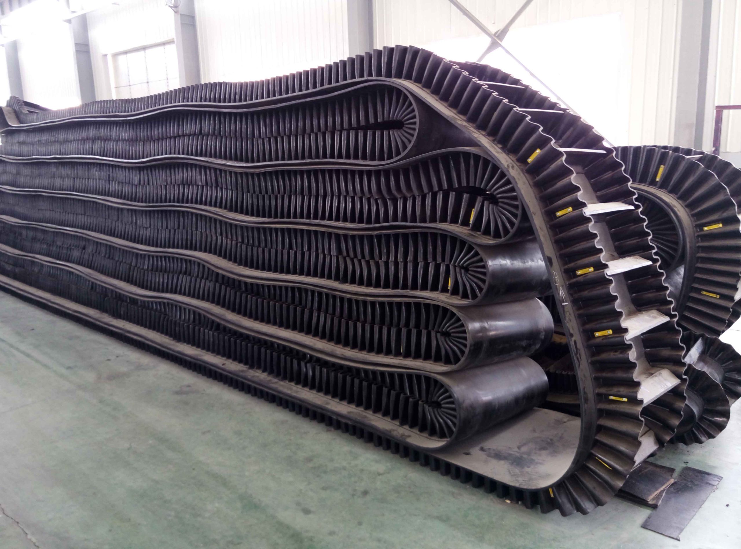
The pulley works together with the conveyor belt, idler roller sets, and conveyor bracket assemblies. The belt carries the load, the idlers support it, and the pulley at the drive or return point supplies the tension and traction. When one of these parts is mismatched, tracking problems and premature cover wear usually follow.
Construction and Surface Options
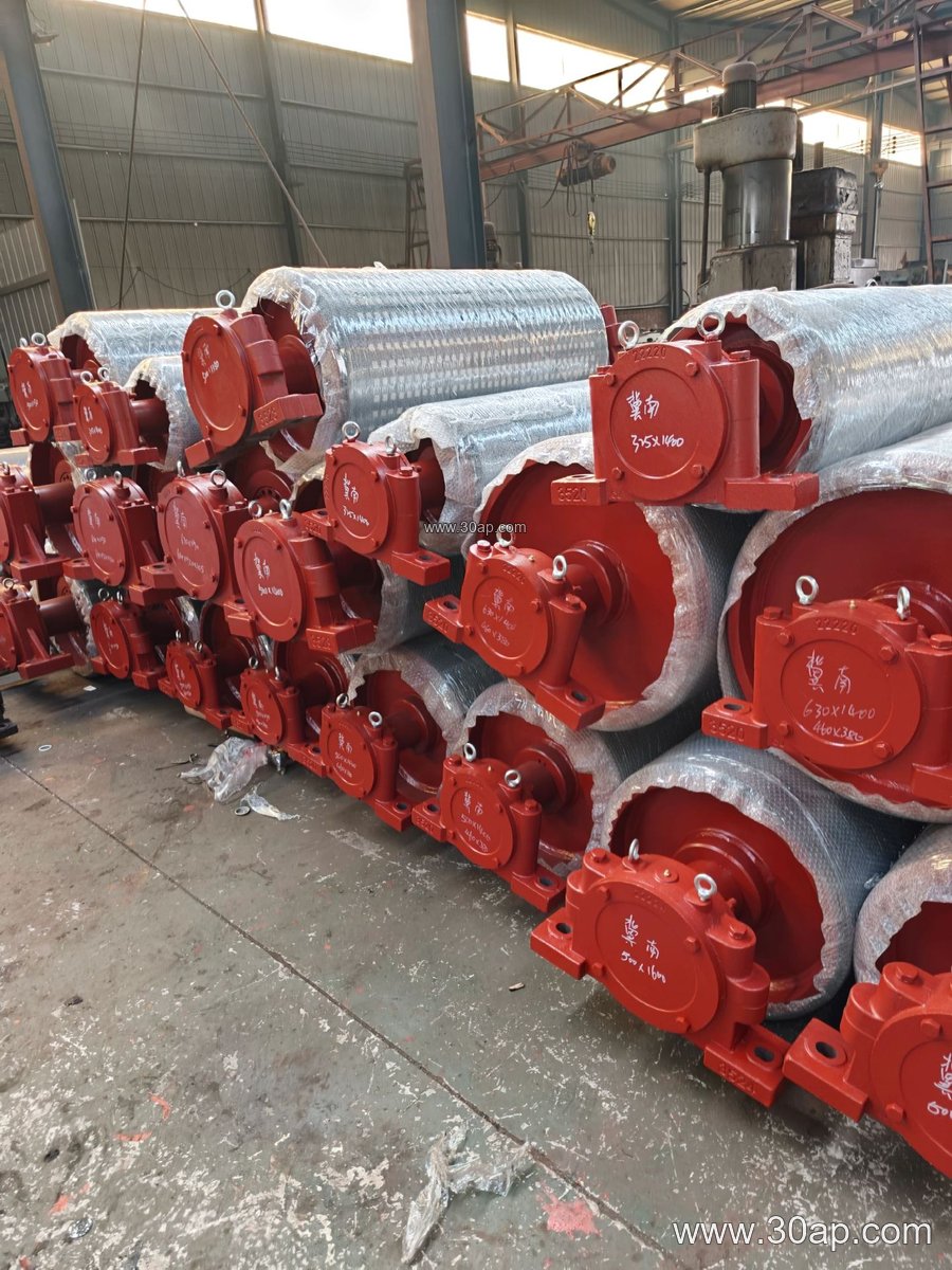
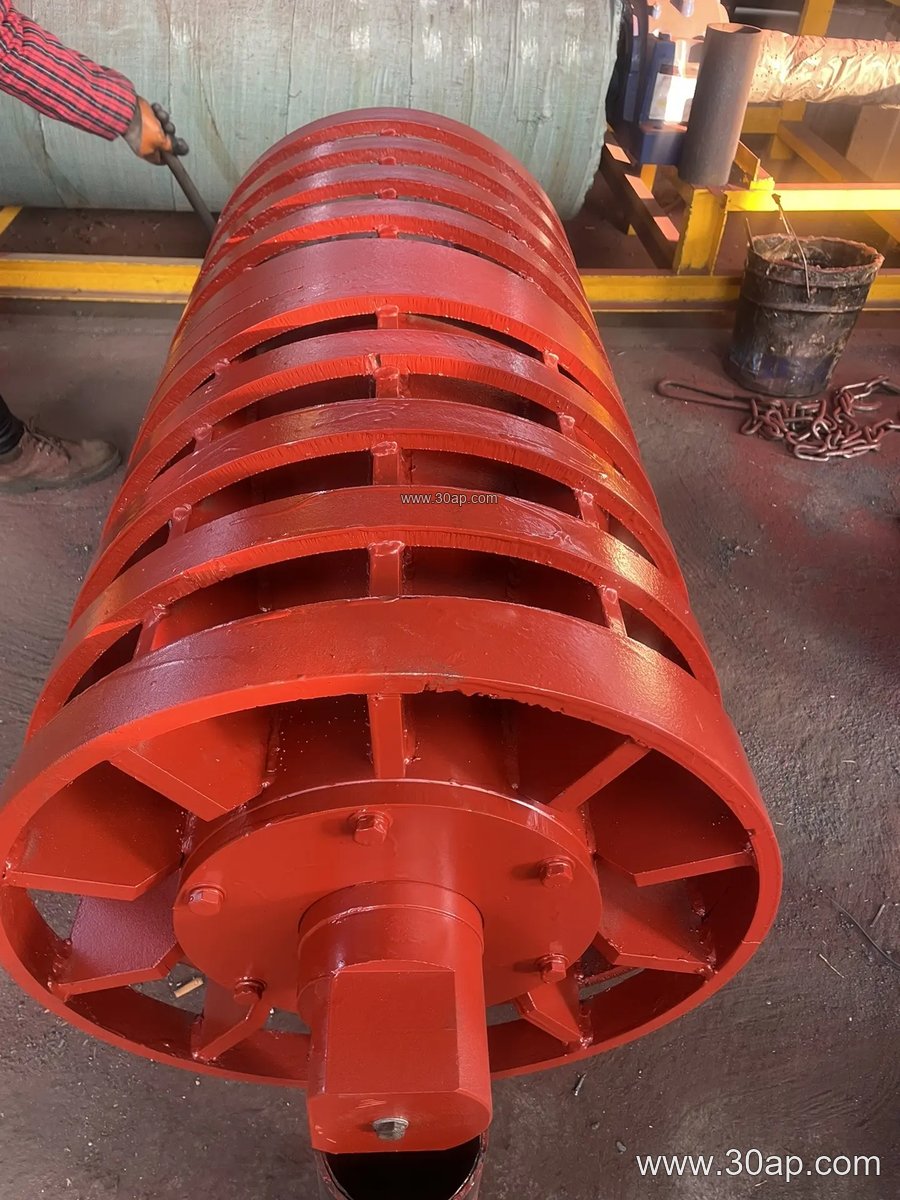
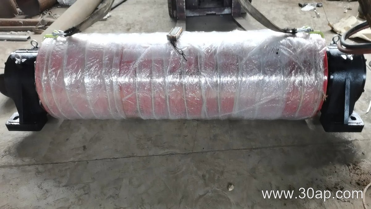
Most units are built around a welded steel shell with end discs, a shaft, and bearing housings. The shell may be machined smooth or covered with rubber, and the cover choice matters in metallurgical service. Common surface forms include:
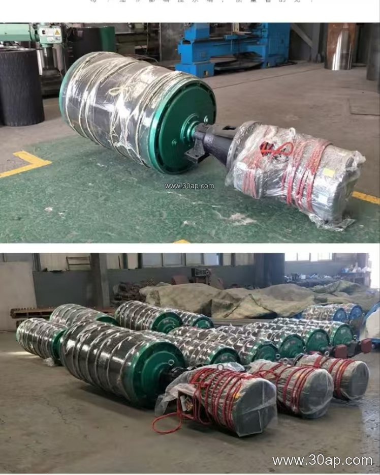
- Plain or smooth shell for light duty and easy cleaning
- Hot vulcanized rubber for strong bond and abrasion resistance
- Cold bonded rubber for faster replacement cycles
- Diamond grooved lagging for wet or dusty conditions
- Herringbone lagging for improved self-cleaning and tracking
- Ceramic lagging for high wear points in ore and sinter duty
Lagging thickness is commonly 8, 10, 12, 15, or 20 mm, chosen with the belt cover and load rather than copied from a catalogue. The shaft diameter is determined by torque and bearing load, not by belt width alone. Typical shaft sizes range from Ø50 to Ø200, but the final value follows the drive calculation.
Where the Drum Fits in the Plant
In a coal preparation plant, the drive pulley at the head end pulls the belt through the discharge zone, while a tail pulley at the loading point keeps the belt aligned. A bend pulley changes belt direction around a transfer tower, and a tension pulley maintains take-up travel. These are different positions with different duties, so a drive drum, tail drum, and bend drum should not be treated as interchangeable. A wing pulley may appear at a discharge point where sticky material needs to release, but it serves a different purpose from the main drive drum.
In a cement plant clinker line or a power station coal yard, the drum face is often wider than the belt. Reference proportions such as B800 with roughly 950 mm face width, B1000 with about 1150 mm, and B1200 with about 1400 mm help in layout planning. Diameter combinations like B800 × Ø500 or B1200 × Ø1000 are common examples, yet no single belt width is tied to one diameter.
Reference Dimensions for Early Planning
The table below gives indicative values only. Final dimensions depend on belt tension, material weight, and the pulley position.
| Belt width | Typical face width | Common diameter range |
|---|---|---|
| B500 | about 600 mm | Ø250 to Ø400 |
| B650 | about 750 mm | Ø315 to Ø500 |
| B800 | about 950 mm | Ø400 to Ø630 |
| B1000 | about 1150 mm | Ø500 to Ø800 |
| B1200 | about 1400 mm | Ø630 to Ø1000 |
| B1400 | about 1600 mm | Ø800 to Ø1250 |
| B1600 | about 1800 mm | Ø1000 to Ø1400 |
What Buyers Should Check
Start with the actual belt tension and the load profile, then confirm the shell thickness, shaft size, bearing type, and lagging pattern. Ask how the pulley will be balanced and whether the face width leaves enough room for belt wander. In a quarry or tunnel muck line, dusty conditions favor sealed bearings and grooved lagging; in a steel mill sinter line, heat and abrasion point toward a heavier cover.
Finally, match the drum to the conveyor bracket and take-up arrangement so alignment can be adjusted during installation. A well specified metallurgical conveyor pulley is not the largest one available; it is the one whose diameter, face width, shaft, and surface suit the belt, the material, and the duty point.