What the Ø108 Self-Aligning Idler Does
The Ø108 self-aligning idler is a training roller built around a 108 mm outside diameter. Its job is to keep the conveyor belt centered on the structure, especially where loading, misalignment, or a curved route tends to push the belt sideways. When the belt drifts, the idler responds and steers it back toward the centerline. In a coal handling line, a quarry transfer point, or a cement plant clinker route, this small correction can reduce edge damage and spillage.
The product is also called a 108 mm self-training idler or a self-aligning return roller, depending on where it sits in the conveyor. It is a distinct idler subtype, not a drive pulley, tail pulley, or bend pulley. Those pulleys transmit power or change belt direction; the self-aligning idler only guides the belt.
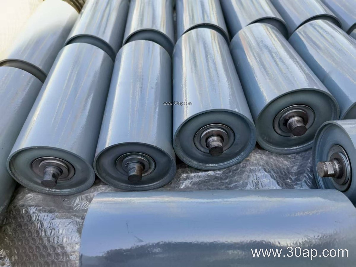
How the Roller Is Built
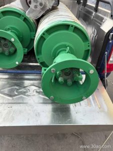
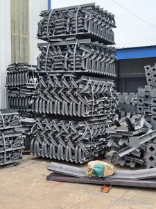
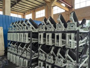
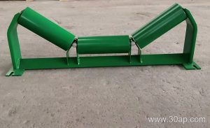
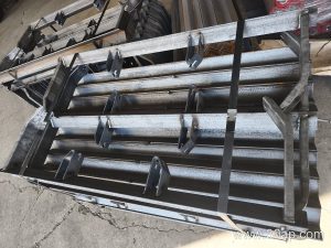
A typical unit combines a steel tube shell, bearing housings, a shaft, and a mounting frame that allows the roller set to pivot. The pivoting action is what makes correction possible: when the belt contacts the roller off-center, the roller set swings slightly and generates a steering force. Friction self-aligning and conical self-aligning designs use different contact geometry to achieve the same tracking goal.
Common construction details include:
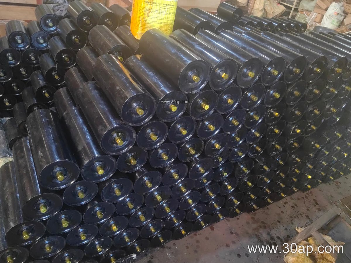
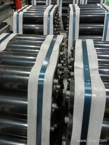
- Shell in steel tube, with nylon, ceramic, or rubber lagging options where extra grip or wear resistance helps.
- Bearing sizes such as 6205, 6305, 6306, or 6308, selected by load and shaft design rather than by roller diameter alone.
- Sealed bearing housings to keep dust out in mining, sintering, and aggregate service.
- A pivoting bracket or frame that mounts to the conveyor structure.
The 108 mm diameter is a common mid-range size. It is not tied to one belt width, and a given belt width can use different roller diameters depending on load, speed, and frame design.
Where It Fits on the Conveyor
Self-aligning idlers are usually installed on the carrying side, sometimes as a three-roll troughing set, and on the return side as a V-type or flat training set. They are most useful at transfer points, after curves, and on long runs where the belt has room to wander. A limestone quarry or a power plant coal conveyor often places them where the belt is most likely to shift.
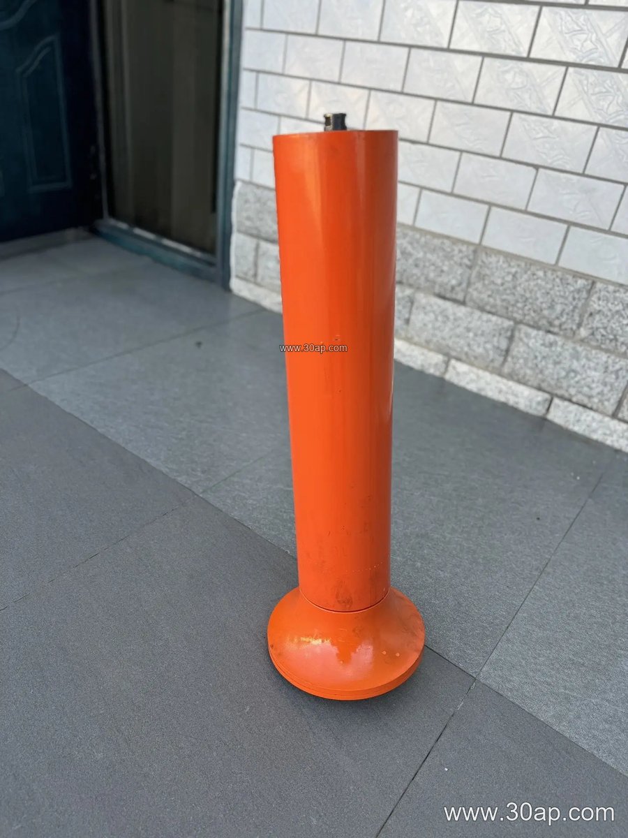
For comparison, a buffer idler absorbs impact at the loading point, while a spiral idler helps clean the belt. Those are different duties; the Ø108 self-aligning idler is chosen for tracking, not impact absorption or cleaning.
Common Reference Dimensions
The table below gives typical reference values. Roller length changes with belt width, trough angle, and roll configuration, so treat these as examples rather than fixed matches.
| Belt width | Typical roll length (three-roll troughing) | Common trough angle |
|---|---|---|
| B500 | about 200 mm | 20° to 35° |
| B650 | about 250 mm | 20° to 35° |
| B800 | about 315 mm | 30° to 35° |
| B1000 | about 380 mm | 30° to 35° |
| B1200 | about 465 mm | 30° to 45° |
| B1400 | about 530 mm | 30° to 45° |
| B1600 | about 600 mm | 35° to 45° |
Side rollers and center rollers can have different lengths, and the frame geometry determines the final fit. A forward tilt of about 1.5° to 2° is sometimes used on training idlers to assist centering.
Buying Notes
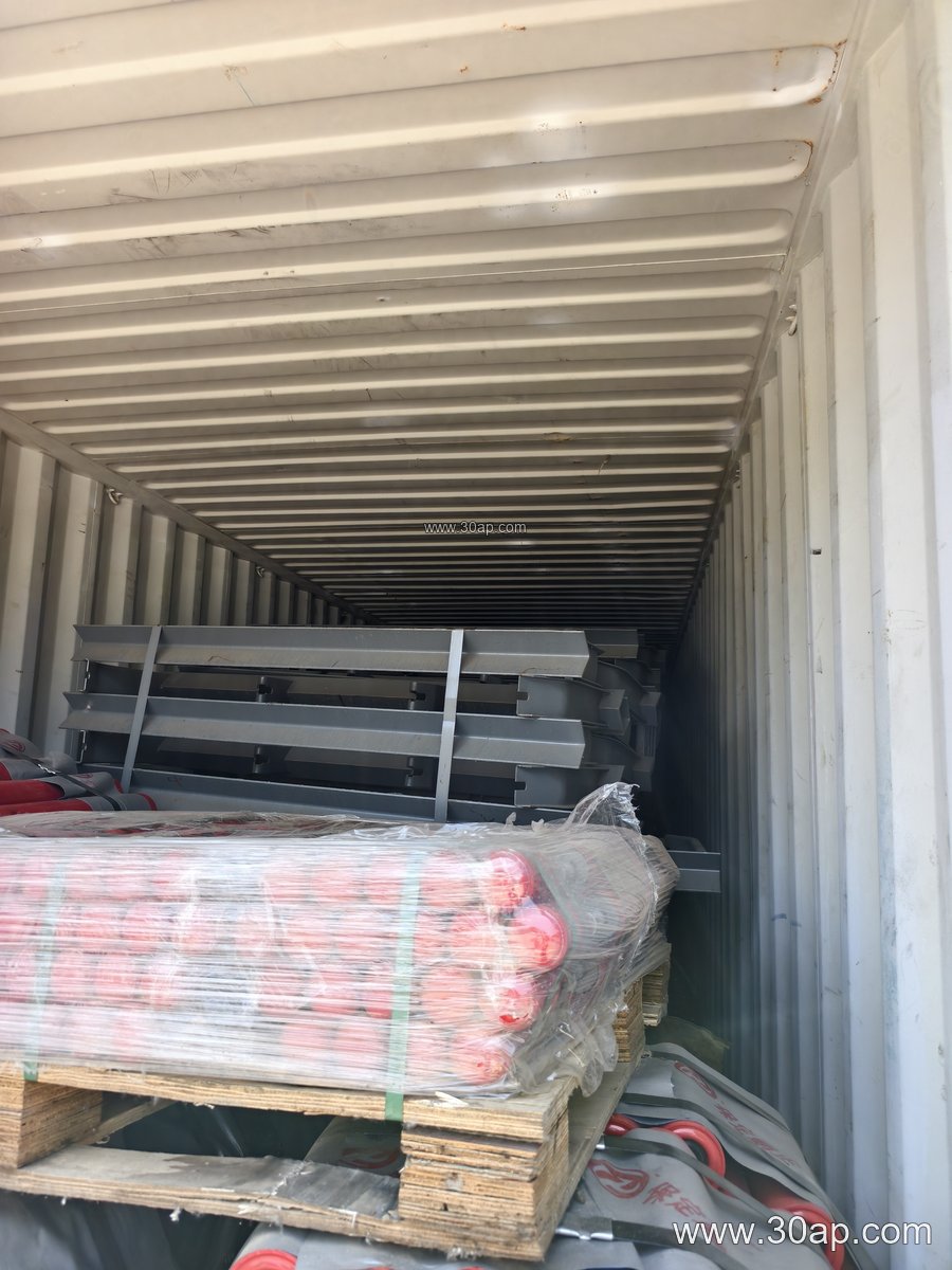
Before ordering a Ø108 self-aligning idler, confirm the belt width, the trough angle, the mounting bracket pattern, and whether the unit is for the carrying or return side. Check the shaft and bearing arrangement against the existing conveyor bracket. Ask for the roller length and frame dimensions rather than assuming they follow from belt width alone.
For dusty service in a coal mine, aggregate plant, or fertilizer handling line, sealed bearings and a wear-resistant shell matter more than a low price. Keep spare rollers on hand and inspect pivoting parts for buildup, since a jammed self-aligning frame cannot correct belt drift.