What a Conveyor Support Leg Does on a Belt Conveyor
A conveyor support leg is the vertical structural member that carries the weight of a belt conveyor’s idler frames, troughing idlers, return rollers and the loaded conveyor belt down to the floor, foundation or steel structure. In a crushing and screening plant, the legs are often the first parts a maintenance crew inspects after a belt mistracks, because a leaning or corroded leg changes the alignment of every idler roller above it. The same component is also called a belt conveyor support leg or conveyor stand leg, and those names refer to the same product.
A leg is not simply a post. It sets the elevation of the idler frame, fixes the stringer spacing, and provides the anchor points that keep a conveyor pulley, drive station and take-up section in line with the rest of the belt line.
How the Leg Is Built
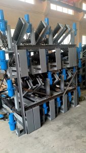
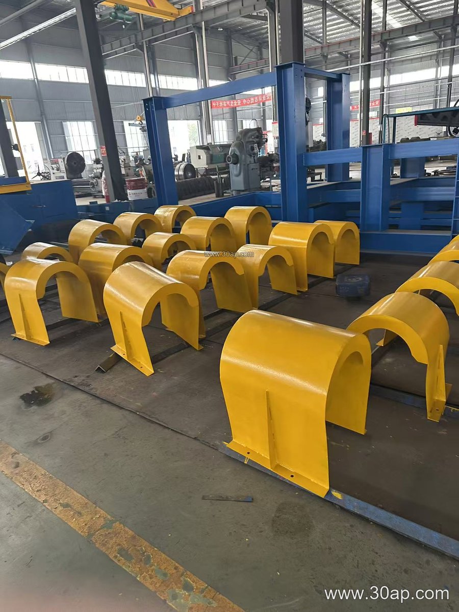
Most support legs are fabricated from angle steel, channel steel or folded steel plate, with a base plate welded at the bottom and a bolted or welded top connection for the stringer or idler frame. Common construction details include:
- Base plate with anchor bolt holes for concrete foundations
- Slotted or drilled top holes so the stringer height can be trimmed on site
- Diagonal bracing between paired legs to resist lateral belt pull
- Hot dip galvanized or painted finish for wet coal, cement dust and coastal air
Height, leg spacing and base plate dimensions follow the conveyor profile and the load on each frame, so they are set by design rather than chosen from a single catalogue number.
Where Support Legs Are Used
Support legs appear wherever a conveyor runs above ground level. In a coal preparation plant they carry the troughing idler frames along the main haulage belt; in a cement plant they support clinker transport lines that pass over walkways and equipment. In a power plant coal yard, a lime kiln feed line or a fertilizer granulation building, the legs are usually bolted to a raised concrete plinth so that spillage can be washed away. Portable and transfer conveyors use shorter, sometimes adjustable legs to match the discharge height of a crusher or screen.
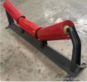
The leg works together with the idler frame, the conveyor bracket that ties the frame to the stringer, and the conveyor belt itself. When a bend pulley or tail pulley is relocated during a plant upgrade, the legs on the approach section usually need re-setting as well.
Frame Types the Legs Carry
Although the leg is the main subject here, its top connection is shaped by the frame it supports. A short comparison helps when reading a drawing:
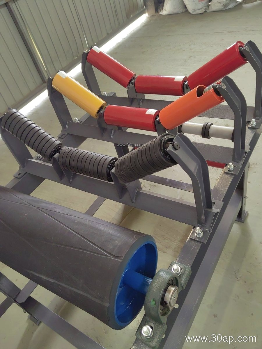
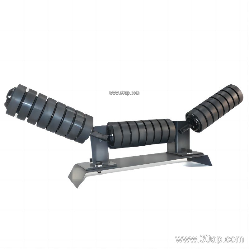
- Troughing idler frame, typically set at 20, 30, 35 or 45 degrees
- Transition frame near the head or tail, where the belt changes from flat to troughed
- Return frame with flat or V-shaped return rollers
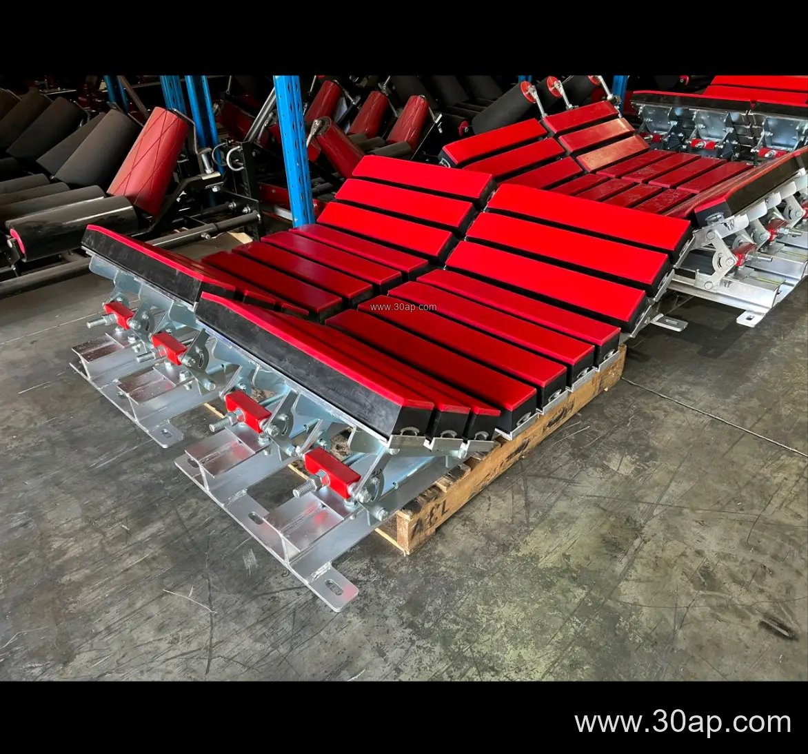
- Impact frame with cushion rollers under the loading point
- Self-aligning frame used to correct belt drift
Each frame type has its own bolt pattern, so the leg top plate should be confirmed against the frame drawing before fabrication.
Common Reference Dimensions
The table below lists typical ranges used in layout discussions. They are reference values, not fixed combinations, and the final figures come from the conveyor design.
| Item | Typical reference values |
|---|---|
| Belt width | B500, B650, B800, B1000, B1200, B1400, B1600, B1800, B2000, B2200 |
| Trough angle | 20, 30, 35, 45 degrees; adjustable frames allow changes within this range |
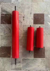
| Idler diameter | Ø89, Ø108, Ø133, Ø159, Ø194 |
| Leg material | Angle steel, channel steel, folded plate |
| Example combinations | B800 with 35 degrees and Ø108; B1200 with 45 degrees and Ø133; B650 with 30 degrees and Ø89 |
Installation hole spacing and crossbeam length change with belt width and trough angle, so they should not be treated as universal constants. A wider belt does not automatically dictate one trough angle or one roller diameter; the material, capacity and transition length all matter.
Fixed or Adjustable Legs
Fixed legs are welded or bolted to a set height and suit permanent lines in a sand and gravel plant or a steelworks sinter line. Adjustable legs use a telescopic section or shim packs and are useful where the belt height must be trimmed after installation, for example at a transfer tower or where a new screen is added later. Adjustable frames can also shift the trough angle between 20 and 45 degrees, which helps when the same structure is reused for a different material. Forward-leaning frames, usually about 1.5 to 2 degrees, are a separate feature of the idler frame and should not be confused with an adjustable leg.
What Buyers Should Check
- Confirm belt width, trough angle and idler diameter so the top plate matches the frame.
- Ask for the leg height measured from base plate to top connection, not overall length.
- Check the anchor bolt pattern and whether the base is designed for a concrete plinth or a steel beam.
- Match the finish to the site: dusty cement, wet coal, or coastal air all call for different protection.
- Verify that bracing is included where the conveyor carries a heavy load or runs at an incline.
- Keep spare legs and base plates for the sections most exposed to spillage and wash-down.
During maintenance, check for loose anchor bolts, bent legs and paint failure at the base, since these are early signs that the frame above may be out of alignment.