What an Impact Resistant Idler Does at the Load Zone
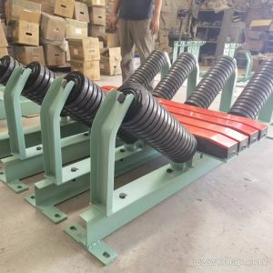
An impact resistant idler is a carrying roller placed where material falls onto the conveyor belt. Instead of a standard steel shell, it uses energy-absorbing rings or a reinforced body to soften the drop. In a quarry, a coal preparation plant, or a cement clinker line, the load zone is where the belt takes the hardest hit. A regular troughing idler may dent, seize, or wear through its shell quickly under that punishment. The impact resistant idler, also called a buffer roller or shock-absorbing idler, is built to take that abuse and keep the belt supported.
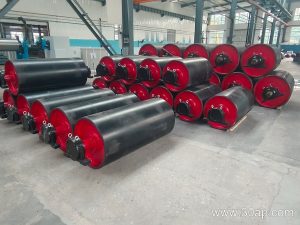
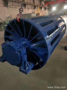
This article stays on that one product family. Drive pulleys, tail pulleys, and bend pulleys are separate components with their own jobs, so they are not covered as replacements here. Where a comparison helps, other roller types are mentioned only to show the difference.
How the Roller Is Built
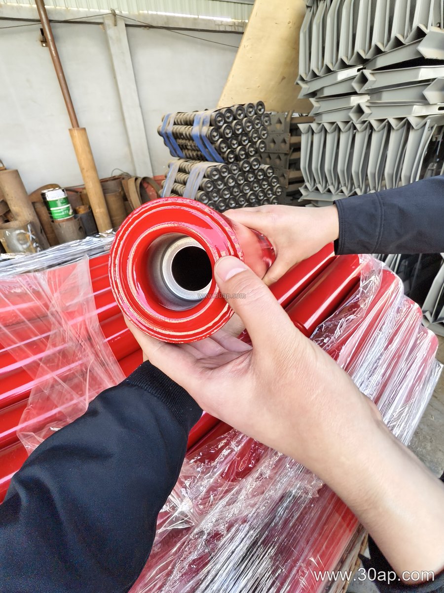
Construction usually starts with a heavy-gauge steel tube, then adds rubber rings, a thicker shell, or a resilient coating. The bearings sit in sealed housings, often with labyrinth or contact seals, because dust and fines are constant at a transfer point. Common bearing sizes include 6204, 6205, 6305, 6306, 6308, and 6310. The bearing number should be matched to the load and the shaft design, not picked from the roller diameter alone.
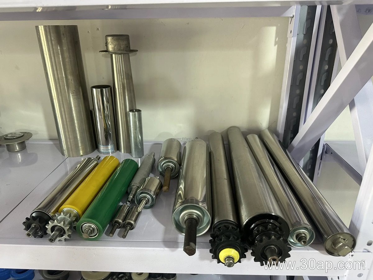
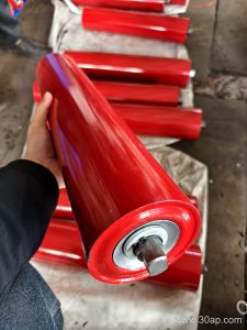
Roller diameters for this family typically range from Ø63 up to Ø219, with Ø108, Ø127, Ø133, and Ø159 being frequent choices in bulk handling. The surface may be plain steel, nylon, ceramic, or rubber rings. Rubber-ring versions are the most common answer when the drop height is significant. A spiral roller is a different subtype used for cleaning the return strand, so it is not a substitute for a buffer roller at the load point.
Where It Fits on the Conveyor
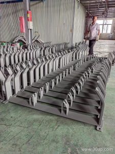
Impact resistant idlers are installed directly under the chute or hopper discharge. They usually appear in three-roll troughing sets, sometimes with a 20, 30, 35, or 45 degree trough angle. The side rollers and center roller may have different lengths. For reference, a three-roll troughing set on B500 belt often uses a roller length near 200 mm, B650 near 250 mm, B800 near 315 mm, B1000 near 380 mm, B1200 near 465 mm, B1400 near 530 mm, and B1600 near 600 mm. These are common examples only, and the final length follows the belt width, trough angle, and roller arrangement.
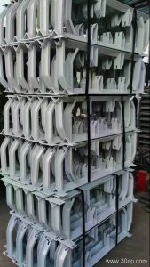
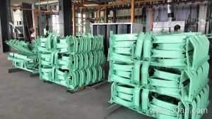
Belt widths run from B400 up to B2400 in many plants. A buffer roller set on B1800 or B2000 will need a longer roller and a stronger bracket than one on B800. The conveyor bracket, sometimes called the idler frame, must handle the added weight of the rubber rings and the shock load.
Typical Industries and Operating Conditions
You will find this roller in limestone mines, iron ore plants, copper concentrators, coal washing plants, aggregate crushing and screening lines, power plant coal handling, steel sinter plants, and tunnel muck removal. The common thread is a high drop height or a heavy lump size. In a sand and gravel pit, for example, a primary crusher discharge can send sharp rock onto the belt with little warning. A rubber-ring impact idler absorbs that energy and reduces belt cover damage.
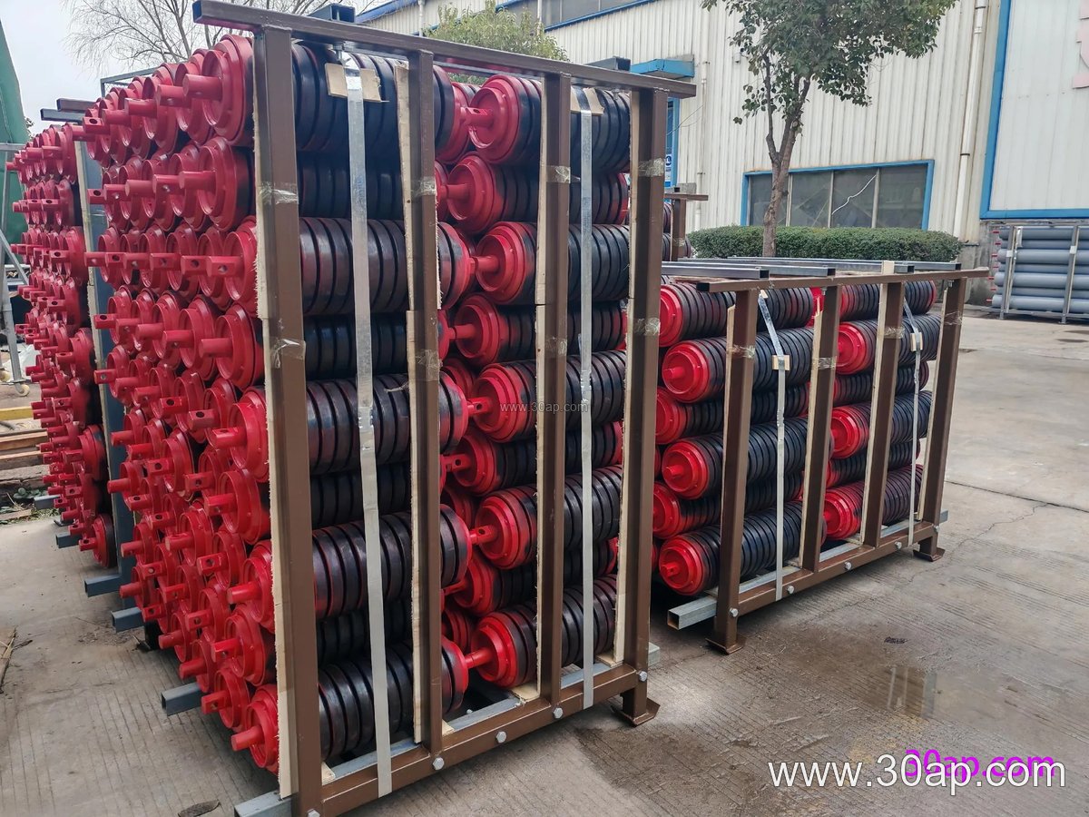
Moisture, fines, and sticky material also matter. A sealed bearing housing helps, but no roller lasts forever if the load zone is misaligned. Keeping the chute centered and the skirt rubber in good condition extends roller life as much as the roller design itself.
Selection Points for Buyers
Before ordering, confirm the belt width, the trough angle, the roller diameter, the shaft size, and the mounting centers. A buffer roller with Ø133 mm shell and 6205 bearings is a different assembly from one with Ø159 mm shell and 6308 bearings. Do not assume that one belt width only matches one roller diameter. The same B1000 belt may run Ø108, Ø127, or Ø133 rollers depending on the conveyor design and load.
- Roller diameter: common options include Ø63, Ø76, Ø89, Ø102, Ø108, Ø127, Ø133, Ø159, Ø178, Ø194, and Ø219.
- Surface form: steel tube, nylon, ceramic, or rubber rings.
- Bearing: 6204, 6205, 6305, 6306, 6308, or 6310, selected by load and shaft.
- Belt width: B400 through B2400, with roller length set by the troughing set.
- Trough angle: 20, 30, 35, or 45 degrees, with forward tilt around 1.5 to 2 degrees only where self-aligning behavior is wanted.
Ask for the shaft diameter and the bracket hole pattern rather than guessing from the belt width. A conveyor pulley at the head end and an impact idler at the load point do different work, and a tail pulley or bend pulley should not be listed as an alternative to a buffer roller. The right choice is the one that matches the drop energy, the material lump size, and the belt width on that specific conveyor.