What a Welded Pulley Is
A welded pulley is a conveyor pulley whose cylindrical shell is joined to its end discs by welding rather than by casting the body as one piece. In everyday plant language it is also called a fabricated pulley, and the two names describe the same component. The shell, the end plates, and the hub are cut, machined, fitted, and then welded into a single rotating body that carries the conveyor belt.
Because the body is assembled from separate parts, a welded pulley can be produced in a wide range of diameters and face widths without new casting patterns. That flexibility is the main reason it appears so often on bulk handling conveyors.
How the Body Is Built
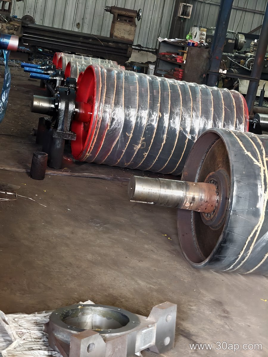
A typical welded pulley starts with a rolled steel shell. The ends are squared, and two dished or flat end discs are prepared with a bore for the shaft or hub. After alignment, the discs are welded to the shell, usually with a continuous fillet or groove weld. The shaft is then fitted, often by shrink fitting or keyed connection, and the assembly is machined so the outside diameter runs true.
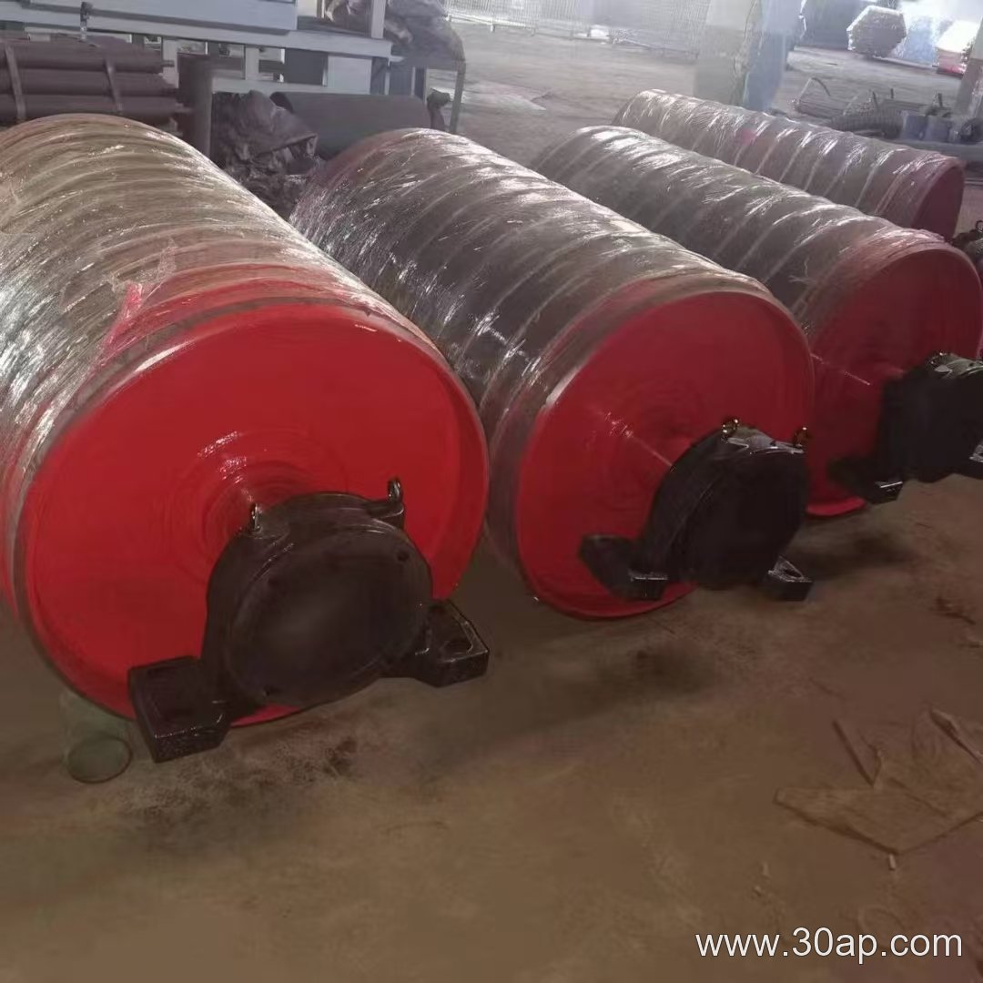
Balance matters as much as strength. An unbalanced pulley vibrates, loads the bearings unevenly, and shortens belt life, so larger units are usually balanced after welding. Surface finish also matters, since a rough shell can wear the belt cover.
Surface Options
- Plain machined face for light duty and clean, dry material
- Rubber lagging applied cold or hot vulcanized to improve grip
- Diamond or herringbone grooved lagging to help shed water and fines
- Ceramic lagging for abrasive duties where slip is a concern
Lagging thickness is commonly 8, 10, 12, 15, or 20 mm, chosen according to the duty rather than copied from a catalogue page.
Where It Fits on a Conveyor
These pulleys are not interchangeable by position. A drive pulley transmits torque from the gearbox to the belt. A tail pulley at the loading end turns freely and supports the belt. A bend pulley changes belt direction, and a tension pulley takes up slack. Each duty changes the load case, so the same shell size may be built with different shafts, hubs, and lagging.
The welded design suits all of these positions. In a quarry or a limestone crushing line, for example, a drive pulley with diamond lagging may pull a heavily loaded belt up an incline, while a bend pulley nearby runs plain and simply redirects the belt path. Similar arrangements appear in coal preparation plants and aggregate screening circuits.
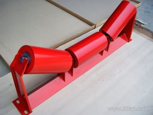
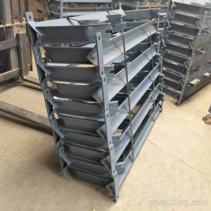
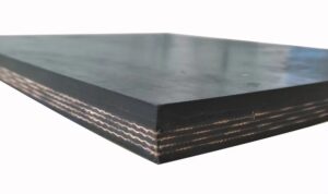
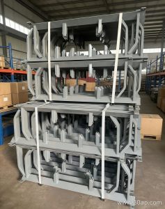
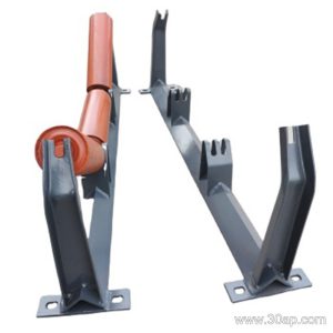
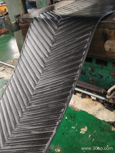
Related hardware usually includes the conveyor belt itself, the idler roller that supports the belt between pulleys, and the conveyor bracket that anchors the bearing housings to the frame.
Sizes and How They Are Chosen
Belt width and pulley diameter are separate decisions. Common belt widths run from B400 up to B2400, and the pulley face is normally wider than the belt, for example about 500 mm face for B400 and about 1400 mm for B1200. Diameter is selected from the belt tension, the wrap angle, and the bending fatigue the belt can accept, with common sizes such as Ø200, Ø315, Ø500, Ø800, Ø1000, and Ø1250 appearing across different duties. A combination like B800 x Ø500 or B1200 x Ø1000 is a design choice, not a rule that ties one belt width to one diameter.
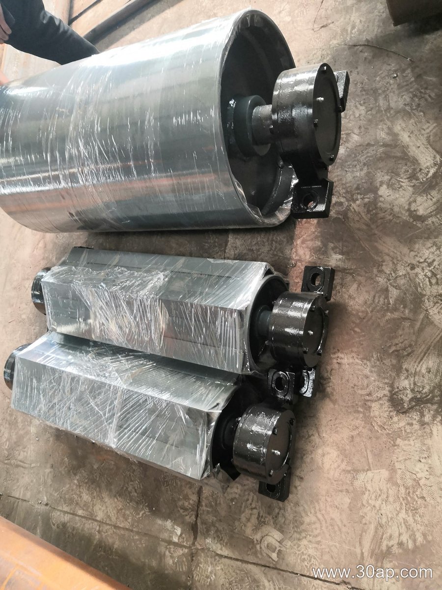
Shaft diameter follows torque and bearing load, not belt width alone. Common shaft sizes include Ø50, Ø60, Ø80, Ø100, Ø120, Ø160, and Ø200, but the final value comes from the drive calculation.
What Buyers Should Check
Before ordering, confirm the position on the conveyor, the belt width, the required face length, the shaft and bearing arrangement, and whether lagging is needed. Ask how the weld is inspected and how the finished pulley is balanced. Also confirm the shaft material and the hub design, because these determine how the pulley handles shock loads from large lumps.
For maintenance, check lagging wear, weld condition, and bearing play at each shutdown. Replacing a worn lagged shell early is usually cheaper than letting a slipping belt damage the drive.