Calculating Structural Dimensions for a Heavy Duty Conveyor Pulley
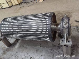
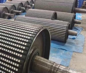
How do design engineers determine the exact physical dimensions required for a conveyor pulley operating under severe industrial conditions? Establishing the correct structural size involves a rigorous mathematical sizing process based on belt tensions, torque requirements, and material fatigue limits. In a heavy mineral-processing plant, a conveyor pulley must withstand continuous mechanical stresses generated by dense iron ore payloads. Because inaccurate sizing leads to premature shaft yielding or shell deformation, engineers rely on structured calculation models governed by established mechanical engineering principles.
Defining Operational Assumptions and Input Parameters
Before initiating any calculation workflow for a conveyor pulley, engineers must establish a clear set of baseline operational assumptions. For this hypothetical mineral-processing plant evaluation, we consider a primary drive unit handling coarse copper ore with a maximum belt tension ($T_1$) of 180 kN and a slack side tension ($T_2$) of 60 kN. The conveyor belt width is specified at 1400 mm, with a rotational speed yielding an angular velocity ($\omega$) of 3.14 rad/s. The center-to-center bearing span ($L$) is assumed to be 1800 mm.
- Maximum tight-side belt tension ($T_1$): 180 kN
- Slack-side belt tension ($T_2$): 60 kN
- Bearing span length ($L$): 1800 mm
- Shell face width ($W_f$): 1500 mm
- Material yield strength ($\sigma_y$): 250 MPa for standard structural steel
Calculating Combined Shaft Bending and Torsional Loads
The primary mechanical sizing task for any conveyor pulley is determining the minimum shaft diameter ($d$) required to resist combined bending moments and torsional shear stresses. The resultant radial load ($F_r$) acting on the conveyor pulley is calculated from the vector sum of the belt tensions. For an arrangement where the belt wraps 180 degrees around the shell, the radial load equals the sum of tight-side and slack-side tensions:
$F_r = T_1 + T_2 = 180\text{ kN} + 60\text{ kN} = 240\text{ kN}$
Assuming a simply supported beam model across the bearing span ($L$), the maximum bending moment ($M$) at the centerline of the conveyor pulley is calculated using the standard formula:
$M = \frac{F_r \times L}{4} = \frac{240\text{ kN} \times 1.8\text{ m}}{4} = 108\text{ kN}\cdot\text{m}$
Next, the torsional moment ($T_t$) transmitted through the shaft is derived from the net effective belt pull ($T_e = T_1 – T_2$) multiplied by the radius of the conveyor pulley ($R$). Assuming a pulley diameter of 800 mm ($R = 0.4\text{ m}$):
$T_e = 180\text{ kN} – 60\text{ kN} = 120\text{ kN}$
$T_t = T_e \times R = 120\text{ kN} \times 0.4\text{ m} = 48\text{ kN}\cdot\text{m}$
Applying Failure Theories to Determine Final Dimensions
To finalize the shaft dimension, engineers apply the Distortion Energy Theory (von Mises yield criterion) to combine the bending moment ($M$) and torsional moment ($T_t$) into an equivalent bending moment ($M_{eq}$):
$M_{eq} = \sqrt{M^2 + \frac{3}{4} T_t^2} = \sqrt{(108)^2 + 0.75 \times (48)^2} = \sqrt{11664 + 1728} = \sqrt{13392} \approx 115.72\text{ kN}\cdot\text{m}$
Using the allowable bending stress ($\sigma_{all}$), which incorporates a standard safety factor ($n = 2.0$) applied to the material yield strength ($\sigma_y = 250\text{ MPa}$):
$\sigma_{all} = \frac{\sigma_y}{n} = \frac{250\text{ MPa}}{2.0} = 125\text{ MPa} = 125 \times 10^3\text{ kN/m}^2$
The required shaft section modulus ($Z$) is calculated as:
$Z = \frac{M_{eq}}{\sigma_{all}} = \frac{115.72\text{ kN}\cdot\text{m}}{125 \times 10^3\text{ kN/m}^2} \approx 0.000925\text{ m}^3 = 925,000\text{ mm}^3$
Relating the section modulus to a solid circular shaft diameter ($d$) via the formula $Z = \frac{\pi d^3}{32}$, engineers solve for $d$:
$d^3 = \frac{32 \times 925,000\text{ mm}^3}{\pi} \approx 9,420,442\text{ mm}^3$
$d = \sqrt[3]{9,420,442} \approx 211\text{ mm}$
Accounting for standard manufacturing increments and keyway reductions, engineers select a nominal shaft diameter of 220 mm for this conveyor pulley assembly.
Shell Thickness and Deflection Verification Checks
Following shaft dimensioning, the cylindrical shell thickness must be verified to prevent radial implosion or localized buckling under high external belt pressures. The uniform radial pressure ($P$) exerted by the tensioned belt on the conveyor pulley face width ($W_f$) is calculated as:
$P = \frac{T_1 + T_2}{R \times W_f} = \frac{240,000\text{ N}}{0.4\text{ m} \times 1.5\text{ m}} = 400,000\text{ Pa} = 0.4\text{ MPa}$
Shell hoop stress ($\sigma_h$) is then evaluated using thin-wall pressure vessel mechanics, where $t$ represents the unknown shell thickness:
$\sigma_h = \frac{P \times R}{t}$
By setting hoop stress equal to the safe allowable membrane stress of the shell steel, engineers determine the minimum plate thickness. In parallel, deflection checks ensure that total angular slope at the bearing seats does not exceed 8 arcminutes, safeguarding internal bearing raceways from edge loading and premature fatigue failure.