What a Head Bend Pulley Does
A head bend pulley is a direction-changing conveyor pulley mounted near the head of a belt conveyor, where it guides the belt around a curve before or after the discharge point. It is a bend pulley, often called a snub or angle pulley, and it works together with the head drive pulley without replacing it. Drive pulleys transmit power, tail pulleys provide return-end support, and bend pulleys only change belt direction, so these roles should not be confused.
The job of this pulley looks simple, yet it affects belt tracking, wrap angle on the head pulley, and the smooth return of the belt. In a crusher discharge line at a quarry, or on a conveyor feeding a transfer tower at a port, a correctly positioned head bend pulley keeps the belt path compact and reduces the chance of the belt rubbing against structure.
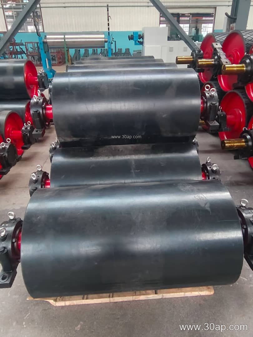
Construction and Surface Options
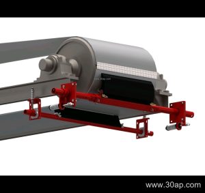
A typical unit is built around a steel drum with welded end discs, a machined shaft, and bearing housings that bolt to the conveyor bracket. The shell may be plain, rubber lagged, or ceramic lagged, depending on whether grip and wear protection matter at that point in the line.
- Shell: rolled steel, sometimes with a slight crown
- Lagging: plain, cold-bonded rubber, hot vulcanized rubber, diamond pattern, herringbone, or ceramic
- Lagging thickness: commonly 8, 10, 12, 15, or 20 mm
- Bearing type: pillow block or flange housing, grease or oil lubricated
- Shaft: sized by torque and load, not by belt width alone
Because the bend pulley often sees a high wrap angle, the lagging and the bearing selection deserve attention. A rubber lagged face can help where the belt is slightly misaligned, while a plain face may suit a clean, well-tracked line.
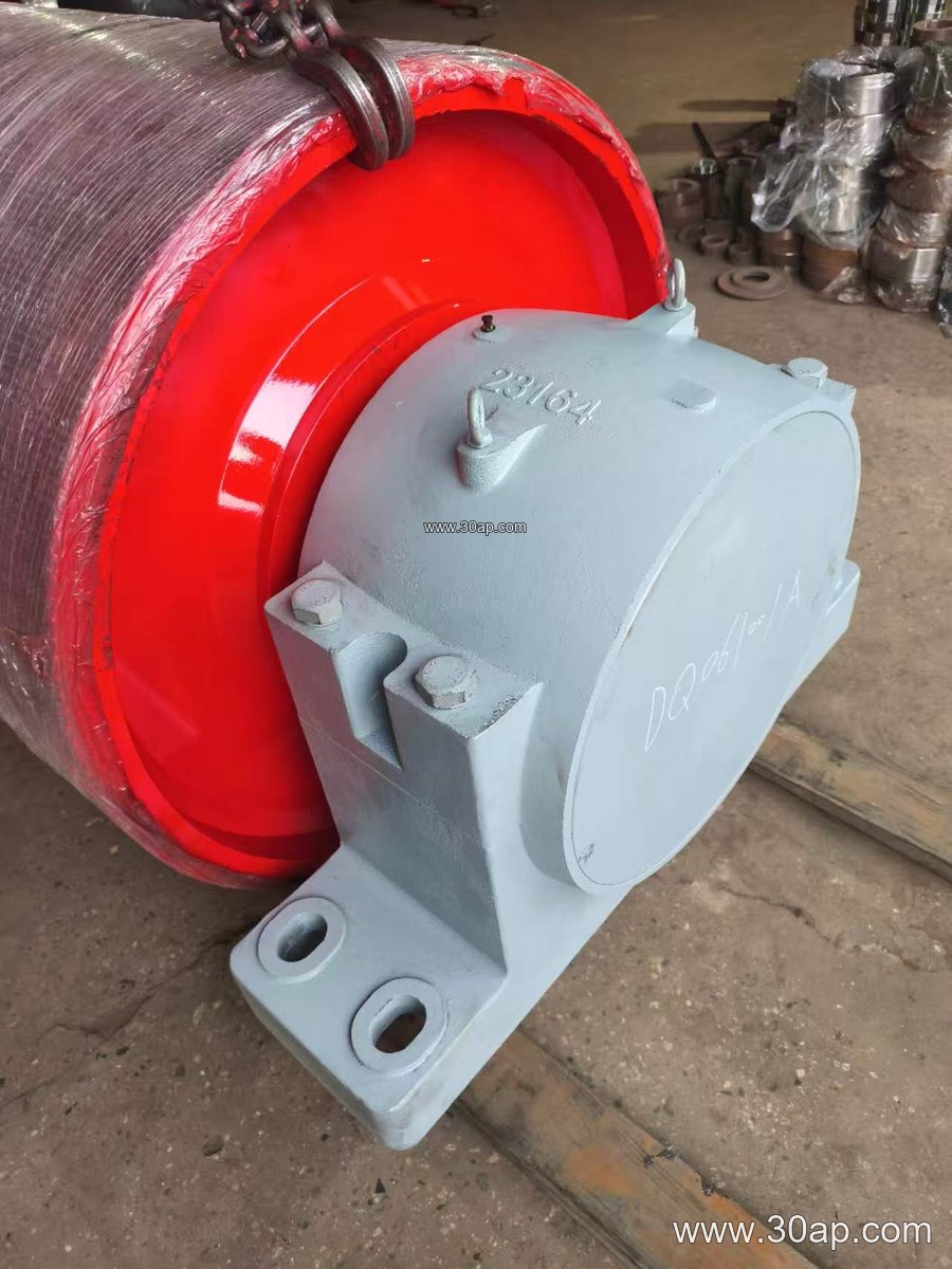
Where It Fits in the Conveyor Layout
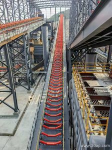
These pulleys appear in many industries. In a coal preparation plant or a power plant coal yard, they help route the belt around the head structure so the discharge chute and the drive unit do not interfere with each other. In a cement plant clinker line or a limestone crushing circuit, they are often placed to increase the contact angle on the head pulley, improving grip when the belt carries a heavy load.
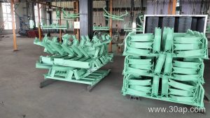
They also show up in sand and gravel plants, iron ore and copper ore handling, fertilizer plants, and grain silos. In each case, the pulley is matched to the conveyor belt, the idler roller spacing, and the frame rather than treated as a standalone part.
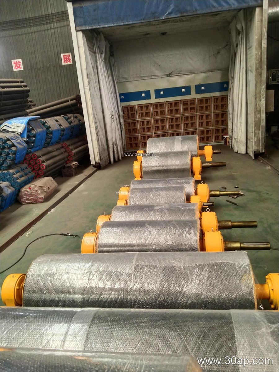
Common Dimensions and Combinations
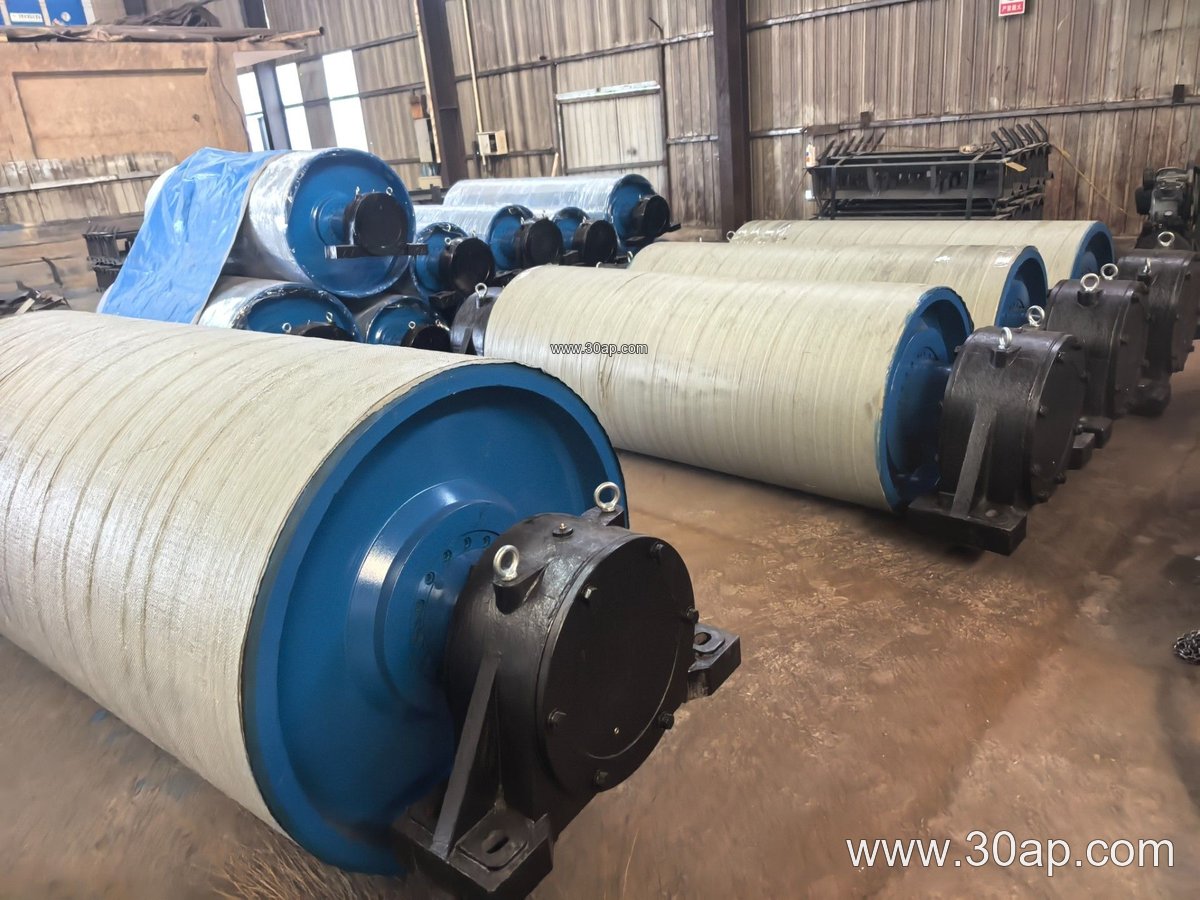
Sizes follow the belt width and the layout. Face width is usually a little wider than the belt, and diameter is chosen from the belt path, tension, and space available. The table below shows reference combinations; these are examples, not fixed rules.
| Belt width | Typical face width | Example pulley diameter |
|---|---|---|
| B400 | about 500 mm | Ø200 to Ø315 |
| B650 | about 750 mm | Ø315 to Ø500 |
| B800 | about 950 mm | Ø400 to Ø630 |
| B1000 | about 1150 mm | Ø500 to Ø800 |
| B1200 | about 1400 mm | Ø630 to Ø1000 |
| B1400 | about 1600 mm | Ø800 to Ø1250 |
| B1600 | about 1800 mm | Ø1000 to Ø1400 |
| B1800 | about 2000 mm | Ø1250 to Ø1600 |
Shaft diameters commonly range from Ø50 to Ø200, but the final value depends on the calculated torque and the bearing load. A B1200 belt may run with a Ø1000 bend pulley on one conveyor and a different diameter on another, depending on the head pulley size and the available space.
Matching the Pulley to the Belt
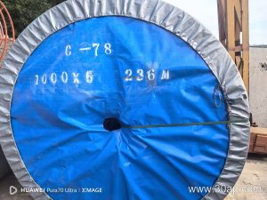
The belt itself influences the choice. A heavy-duty mining conveyor belt carrying ore needs a sturdy shell and well-sealed bearings, while an EP conveyor belt on a shorter run may allow a lighter build. In dusty or wet conditions, a rubber lagged face can improve tracking, and in abrasive service a ceramic lagging may last longer. Where the belt is a flame retardant conveyor belt in an underground coal mining conveyor, the pulley assembly should be selected with the same care for fire safety and dust control.
Belt tension, belt speed, and the wrap angle all affect the load on the shaft. The pulley should be checked against the actual conveyor design rather than copied from a neighboring line.
Buyer Checklist
- Confirm the function: head bend pulley, not a drive or tail pulley
- State belt width and the required face width
- Provide the layout, wrap angle, and head pulley diameter
- Specify lagging type and thickness if grip or wear protection is needed
- Confirm shaft size from torque and bearing load
- Check bearing housing style and lubrication method
- Ask for dynamic balancing and inspection records where relevant
Buyers sourcing through a conveyor components supplier should also confirm how the pulley mounts to the conveyor bracket and whether the bearing centers match the existing frame. A well-matched head bend pulley keeps the belt path clean and extends the service life of both the belt and the head pulley.