What a Three-Roll Idler Bracket Does
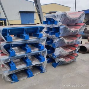
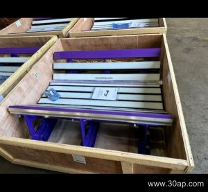
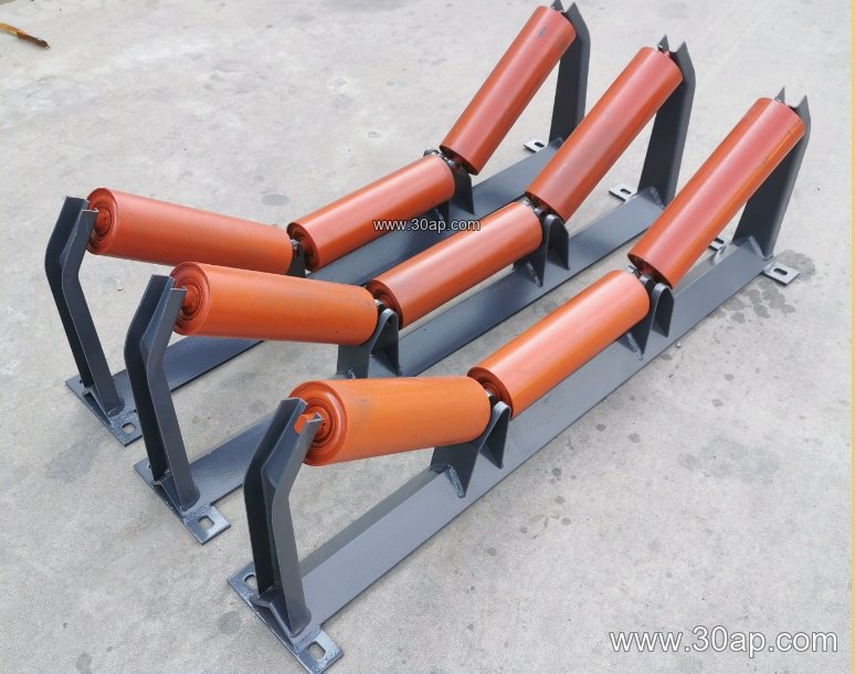
A three-roll idler bracket is the support frame that holds three idler rollers in a troughed arrangement under the carrying side of a conveyor belt. The two outer rolls sit at an angle, and the center roll sits flat or nearly flat, so the belt forms a trough that keeps bulk material centered during transport. In everyday plant language, this part is also called a troughing idler frame or a three-roll carrying bracket. It is a structural component, not a roller itself, and it works together with the idler roller, the conveyor belt, and the surrounding conveyor bracket system.
Because the bracket sets the roll positions, it directly influences belt tracking, material spillage, and how evenly the load is distributed across the roller faces. A poorly aligned frame shows up quickly as edge wear, off-center loading, or noisy running.
How the Bracket Is Built
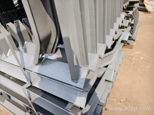
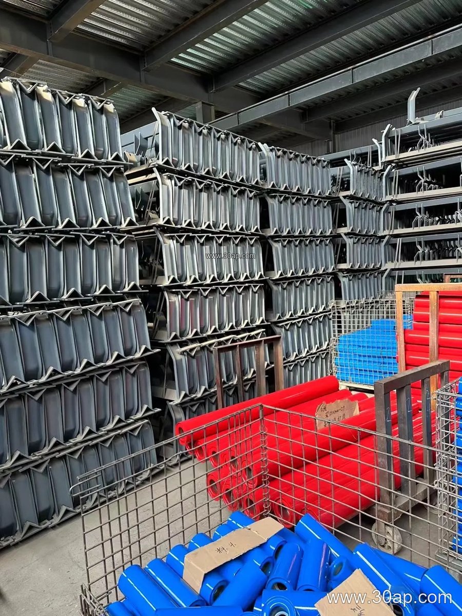
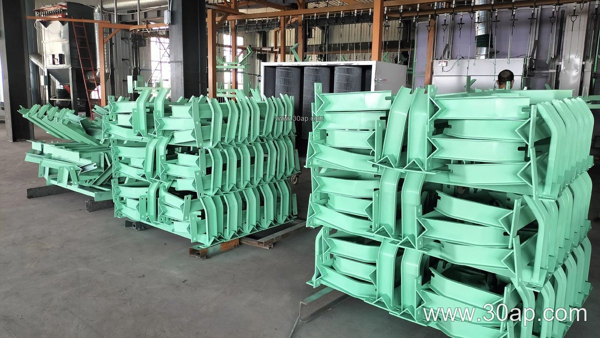
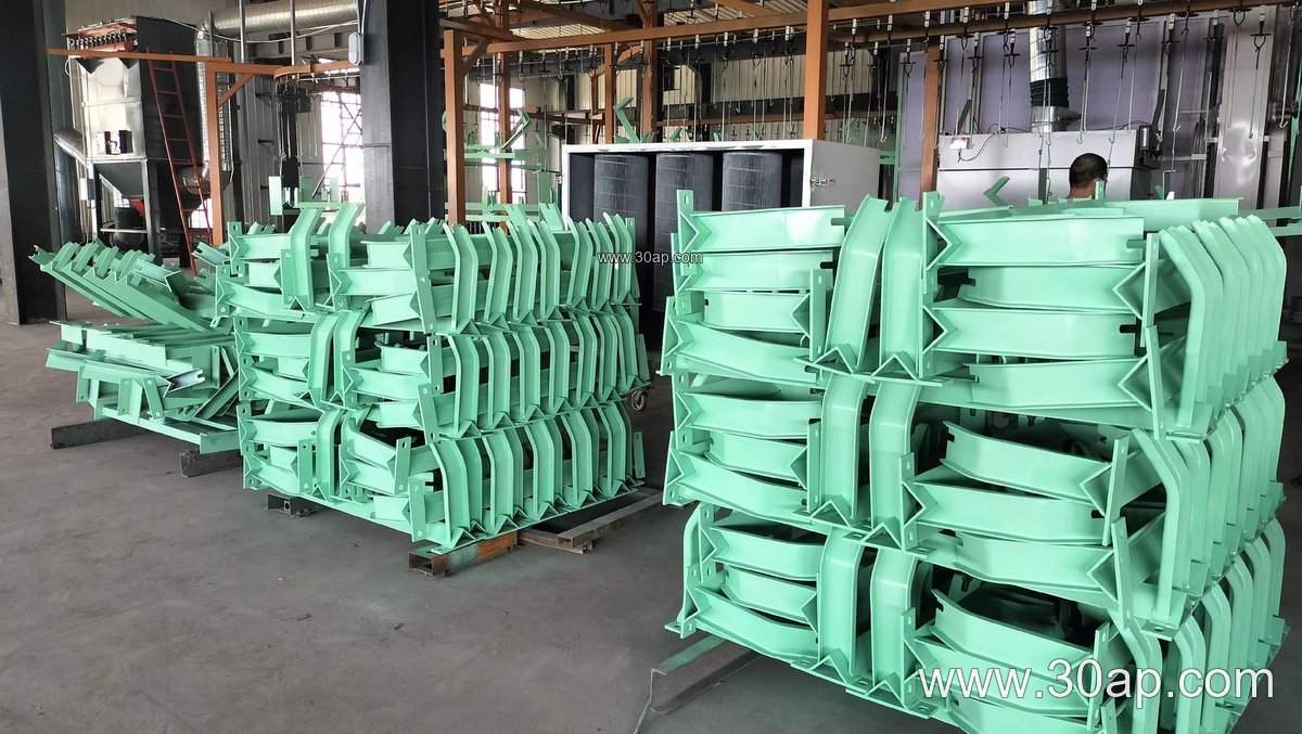
Most three-roll idler brackets are fabricated from angle steel, channel steel, or folded steel plate. The frame usually includes a crossbeam, two inclined end supports, and mounting slots or holes for the roller shafts. Welded construction is common, and the contact surfaces are often painted or galvanized depending on the environment.
Key build details a buyer should check include:
- Roller shaft seating and slot dimensions, which must match the chosen idler roller end fittings
- Trough angle accuracy, since small errors change belt contact across all three rolls
- Weld quality and plate thickness, especially on heavy-duty mining conveyor frames
- Mounting hole spacing, which is determined by belt width and trough angle rather than a single fixed number
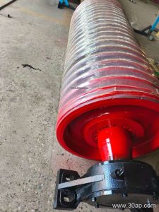
The bracket does not carry the belt directly; it positions the rollers that do. That distinction matters when comparing it with a return bracket or a V-return frame, which support the belt on the return strand instead.
Common Configurations and Reference Dimensions
Three-roll brackets are usually described by belt width, trough angle, and roller diameter. The values below are common reference ranges, not universal specifications.
| Parameter | Typical Options |
|---|---|
| Belt width | B500, B650, B800, B1000, B1200, B1400, B1600, B1800, B2000, B2200 |
| Trough angle | 20°, 30°, 35°, 45° |
| Roller diameter | Ø89, Ø108, Ø133, Ø159, Ø194 |
| Frame material | Angle steel, channel steel, folded steel plate |
| Adjustability | Fixed or adjustable trough angle |
For example, a B800 frame with a 35° trough and Ø108 rollers is a common medium-duty combination, while a B1200, 45°, Ø133 arrangement suits wider belts carrying heavier loads. These are examples only; belt width does not lock a frame to one angle or one roller diameter. Adjustable brackets allow the trough angle to be changed within the listed range, which helps when material characteristics change.
Where It Fits in the Conveyor
The three-roll idler bracket is used on the carrying run of a troughed conveyor. You will find it in a limestone quarry feeding a crusher, in a coal handling section of a power plant, and along aggregate belts in a sand and gravel line. In a cement plant it supports belts moving clinker and raw meal; in a steel plant it appears on sinter and coke transport lines.
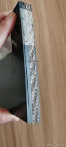
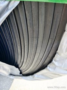
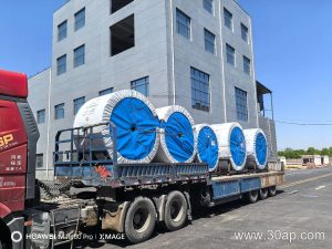
Selection should follow the belt and the duty. An abrasion resistant conveyor belt carrying sharp rock needs stable roll alignment, while a heat resistant conveyor belt on clinker service needs frames that tolerate thermal cycling without distorting. On long overland lines, a steel cord conveyor belt may call for closer frame spacing and more precise angle control. Where fine material is loaded, an impact resistant conveyor belt combined with buffer rollers and matching brackets reduces shock at the transfer point.
Buyer Checklist
Before ordering, confirm the belt width, the required trough angle, and the roller diameter, then verify shaft end dimensions against the idler roller supplier. Ask whether the frame is fixed or adjustable, and check the mounting hole spacing against the existing stringer or conveyor bracket layout. Confirm the steel grade and finish for the site: a wash plant and a dry cement kiln area place very different demands on a frame.
Also consider maintenance access. A frame that allows a single roller to be lifted out without removing the whole bracket saves time during shutdowns. Spare parts should match the original angle and hole pattern so that mixed batches do not create tracking problems later.