What an Idler Bracket Does on a Conveyor
An idler bracket is the structural interface that holds a conveyor idler roller in position on the conveyor frame. It carries the load path from belt and material down into the stringer or beam, and it sets the geometry that shapes the belt into a trough or supports it on the return run. In a quarry or a stone crushing line, a poorly aligned bracket shows up quickly as belt wander, spilled aggregate and edge wear. In a cement plant or a power plant coal yard, the same part affects dust control and belt tracking over long distances.
The bracket is not a wear part in the way a roller shell is, but it must survive vibration, grit and occasional impact. Most mining conveyor belt systems, including underground coal mining conveyor belt installations, rely on a large number of these brackets to keep every roller at the correct angle and spacing.
How the Bracket Is Built
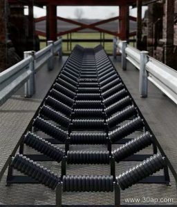
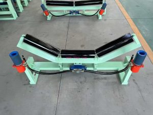
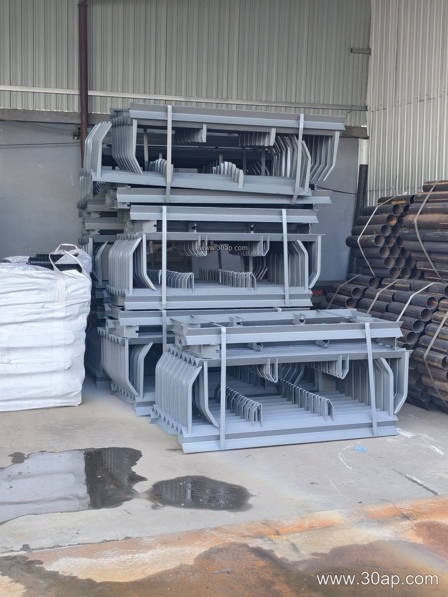
Fabrication usually starts from angle steel, channel steel or bent steel plate, welded or bolted into a shape that matches the frame. A carry-side bracket typically has two or three mounting points for rollers, with the outer rollers inclined to form the trough. A return bracket may hold a single flat roller or a pair of rollers in a V arrangement. Bolt slots are commonly slotted rather than fixed holes so that minor frame and stringer tolerances do not force the roller out of alignment.
Common construction details include:
- Welded angle or channel frame with drilled or slotted mounting holes
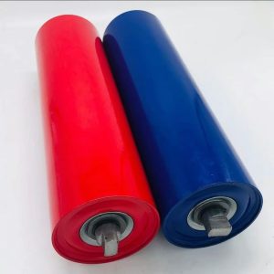
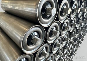
- Roller cradles shaped to match the shaft end and bearing housing
- Powder coating or painting for general duty, galvanizing for wet or coastal sites
- Reinforced versions for impact zones under crusher discharge
On a heavy-duty mining conveyor belt line, brackets near the load point are often heavier than those on the long carry sections, because impact from coarse rock is concentrated there.
Trough Angle and Roller Diameter Choices
The trough angle and roller diameter are usually selected together with belt width. A 20 or 30 degree trough suits many medium-width belts, while 35 and 45 degree troughs are common where higher capacity and better material containment are needed. Adjustable brackets allow the trough angle to be changed within a range after installation, which helps when a belt is being re-tensioned or when material characteristics change.
Roller diameters such as Ø89, Ø108, Ø133, Ø159 and Ø194 are typical references, but the correct combination depends on belt width, belt speed, load and frame design. A B800 belt is not restricted to one angle or one roller size, and a B1200 or B1400 frame may use different roller arrangements in different sections of the same conveyor. Forward-tilted brackets, usually around 1.5 to 2 degrees, are sometimes used to help belt tracking.
Matching Brackets to Belt and Roller Hardware
Brackets must fit the roller shaft ends and the stringer spacing. When specifying, it helps to confirm the belt width, the trough angle, the roller diameter and the mounting hole spacing together. A B650 line with 30 degree troughs and Ø89 rollers needs different bracket dimensions from a B1000 or B1200 line running 35 degree troughs and Ø108 or Ø133 rollers. Installation hole spacing and crossbeam length usually vary with belt width and trough angle, so these should be confirmed against the frame drawing rather than assumed.
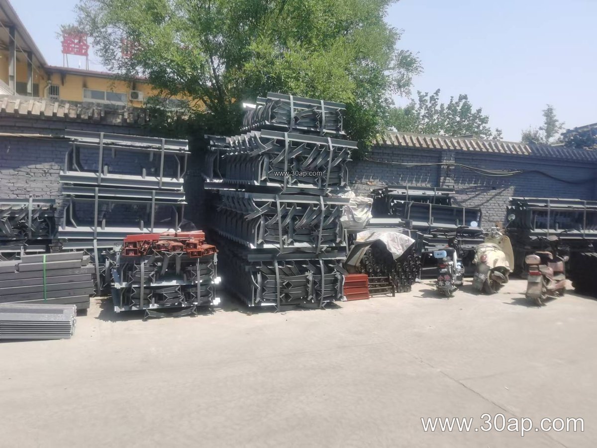
Brackets also need to suit the belt they carry. A thick, abrasion resistant conveyor belt used in an iron ore or copper ore operation imposes different loads from a lighter EP conveyor belt in a recycling or sand making plant. Heat resistant conveyor belt and oil resistant conveyor belt installations may call for brackets that keep rollers clear of hot or oily material buildup. In food grade or clean applications, smooth surfaces and easy cleaning matter more than heavy reinforcement.
Where These Brackets Are Used
Typical locations include the carry side of a long overland conveyor, the transition zone where the belt changes from flat to troughed, the return run, and the load point beneath a crusher or screen. In a limestone mine or aggregate plant, transition brackets help prevent belt stress at the head and tail. In a steel plant or sintering line, V-return brackets keep the return belt centered. In a port ship loading conveyor, self-aligning brackets reduce the need for manual adjustment.
Brackets are also used with pipe conveyor belt and corrugated sidewall conveyor belt systems, where the frame geometry is more specialized and bracket dimensions must follow the manufacturer’s design.
Buyer Checklist
- Confirm belt width, trough angle and roller diameter as a set, not separately
- Check mounting hole spacing and crossbeam length against the existing frame
- Decide between fixed and adjustable brackets based on tracking needs
- Choose material and finish for the site: dusty, wet, coastal or high-impact
- Confirm that the bracket accepts the shaft end of the selected idler roller
- Plan spare brackets for impact zones and transition areas
For a coal mining conveyor belt or an underground mining conveyor belt, flame retardant and anti-static properties of the belt are critical, but the bracket still needs to hold rollers firmly and resist corrosion from wash-down and humidity. Similar checks apply to a cement conveyor belt or a power plant conveyor belt, where dust and heat are constant concerns.
For more information on conveyor brackets, idler rollers and compatible belting, visit the conveyor components section of the site.