What a Conveyor Support Leg Does
A conveyor support leg is the vertical member that carries the weight of a belt conveyor frame down to the floor, foundation, or steel structure. It is the connection between the horizontal stringers and the ground, and it sets the working height of the whole line. In a quarry, a cement plant, or a power plant coal yard, these legs are what keep the idler frames, the conveyor pulley assemblies, and the loaded belt at a consistent elevation along the run.
Although the part looks simple, it is a load path component. The leg receives vertical load from the belt, material, and idlers, plus horizontal forces from starting, braking, and belt tracking. That is why the design of the leg, its base plate, and its bracing should match the frame it supports rather than being treated as an afterthought.
How the Leg Is Built
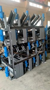
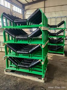
Most support legs are fabricated from angle steel, channel steel, or folded steel plate. A typical leg has a top plate or bracket that bolts to the stringer, a vertical post, and a foot plate with holes for anchor bolts. Taller legs often include diagonal bracing or a cross member between paired legs to control sway.
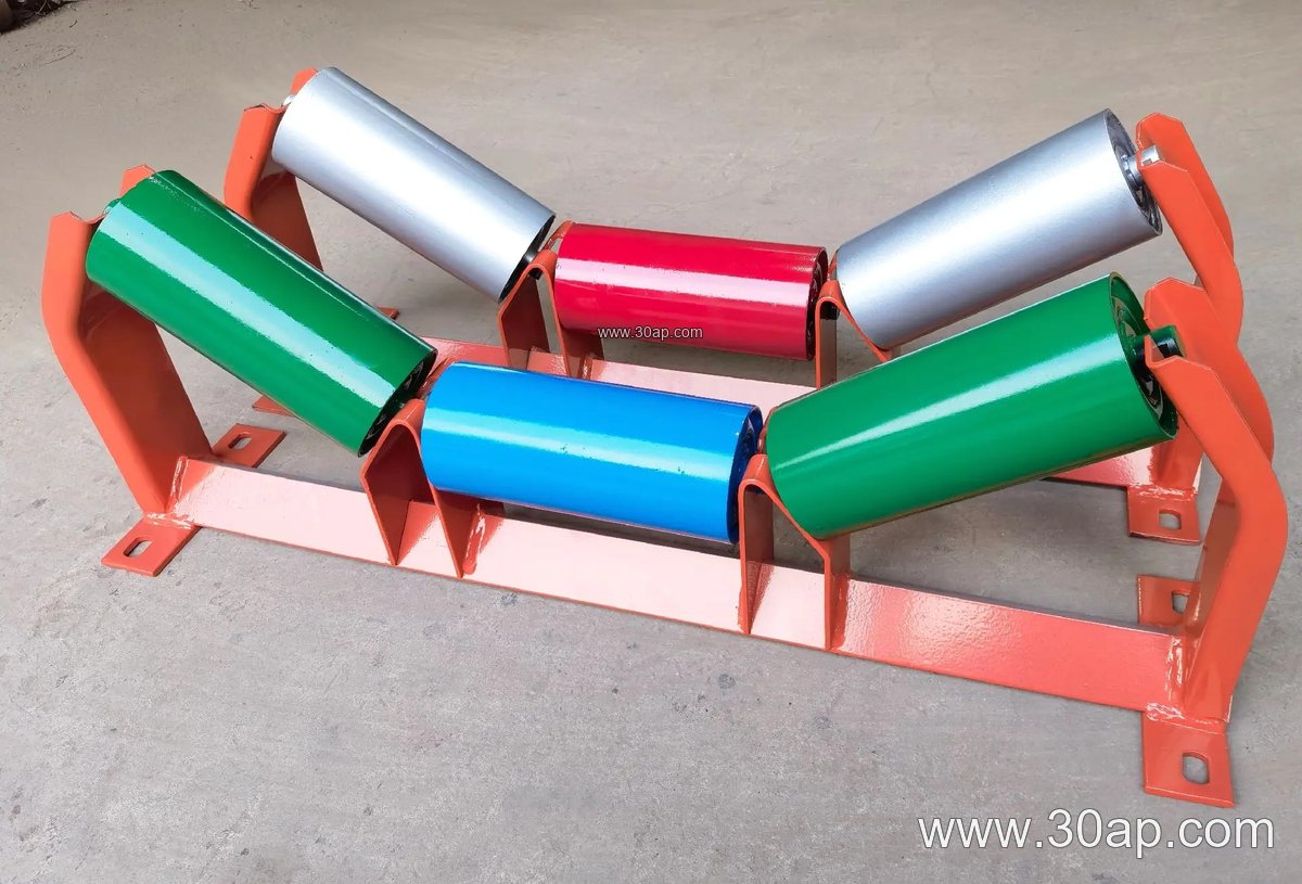
The connection details matter. A conveyor bracket at the top should align with the stringer hole pattern, and the foot plate should be large enough to spread load into the concrete or steel beam below. On long overland lines and in crusher discharge areas, adjustable legs with slotted holes or threaded sections allow the frame height to be trimmed during installation and after foundation settlement.
Common Materials and Forms
- Angle steel legs for light and medium frames
- Channel steel legs for heavier spans and impact zones
- Folded plate legs for clean profiles and higher stiffness
- Fixed legs and adjustable legs with height take-up
Where Support Legs Are Used
You will find them under troughing idler frames on a stone crushing line, beneath return frames in a cement clinker transport gallery, and along transfer towers in a port ship loading system. In a coal preparation plant they carry frames that support a flame retardant conveyor belt in a gallery, while in an iron ore yard they hold heavy frames under an abrasion resistant conveyor belt handling lump ore.
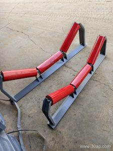
They also appear in less obvious places: a fertilizer plant with a corrosion concern, a grain silo gallery, a tunnel muck removal line, and a steel plant sinter strand discharge. In each case the leg is matched to the local frame type, whether that is a troughing bracket, a V-return bracket, or a self-aligning frame.
Matching the Leg to Frame and Belt
Selection starts with the belt width and the idler diameter, because these set the frame width and the load per leg. The table below gives common reference combinations; actual hole spacing and crossbeam length are determined by design, not by a fixed rule.
| Belt Width | Trough Angle | Idler Diameter | Typical Leg Use |
|---|---|---|---|
| B500 | 20 degrees | Ø89 | Light aggregate and sand lines |
| B650 | 30 degrees | Ø89 | Small quarry and mixing plant frames |
| B800 | 35 degrees | Ø108 | General crushing and screening duty |
| B1000 | 35 degrees | Ø108 | Cement and coal handling galleries |
| B1200 | 45 degrees | Ø133 | Heavy bulk material lines |
| B1400 | 45 degrees | Ø133 | Ore and port transfer conveyors |
| B1600 | 45 degrees | Ø159 | High capacity mining frames |
| B1800 | 45 degrees | Ø159 | Large tonnage primary haulage |
| B2000 | 45 degrees | Ø194 | Extra wide heavy duty structures |
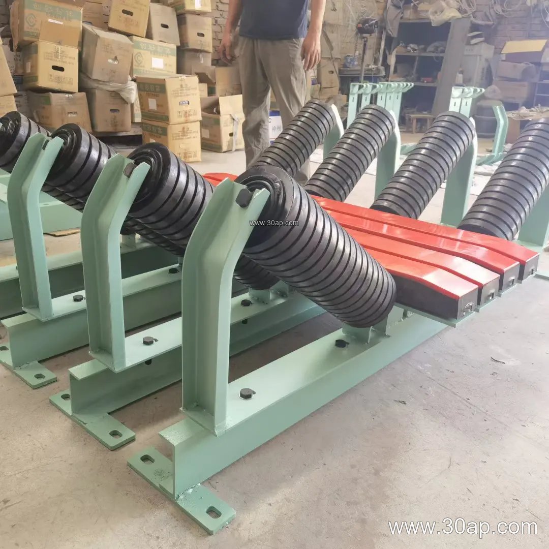
A support leg does not work alone. It sits under a frame that holds conveyor idler rollers, and the frame is positioned relative to the drive and tail pulleys. A change in leg height affects belt line height, so the leg drawing should be read together with the general arrangement of the conveyor.
Buyer Checklist
- Confirm the belt width, trough angle, and idler diameter the frame is designed for.
- Check whether the leg is fixed or adjustable, and what height range is needed.
- Ask for the top bracket hole pattern and the foot plate hole pattern as drawings.
- State the environment: washdown, dust, corrosive fertilizer, or cold climate.
- Confirm bracing requirements for tall legs and for frames near a crusher or transfer point.
- Check galvanizing or painting requirements for outdoor and port installations.
Legs are often ordered together with the frame and the idlers, so it helps to buy them as a matched set. A frame built for a multi-ply fabric core belt or a steel cord belt may carry different loads, and the leg spacing should follow the structural calculation. For reference on the belt side, see conveyor belt and idler roller pages; the leg simply has to carry what those components impose on the frame.
Finally, plan the anchor bolts and grouting before the legs arrive. A correctly sized support leg fixed to a sound foundation is the quiet part of a reliable conveyor, and it is far cheaper to get right at the drawing stage than after the belt has been tracked and loaded.