What an Impact Idler Bracket Does
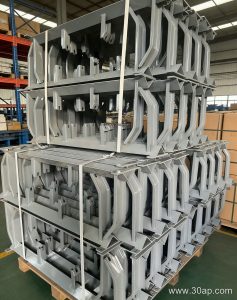
An impact idler bracket is the supporting frame that holds the impact rollers directly beneath the loading point of a conveyor belt. Its job is to keep those rollers in the correct position while absorbing the force of falling material, so the belt does not bottom out against the structure. In a quarry, a coal preparation plant, or a crushing and screening line, the drop from a chute or crusher can be severe, and this bracket is what carries that punishment into the frame instead of into the belt carcass.
The bracket also sets the trough angle at the load zone, which means it influences how well the belt contains the material stream. A poorly supported impact station lets lumps press the belt onto the rollers and frame, accelerating cover wear and splice fatigue. For this reason, the impact idler bracket is usually treated as a wear part rather than a permanent fixture.
Construction and Mounting
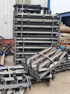
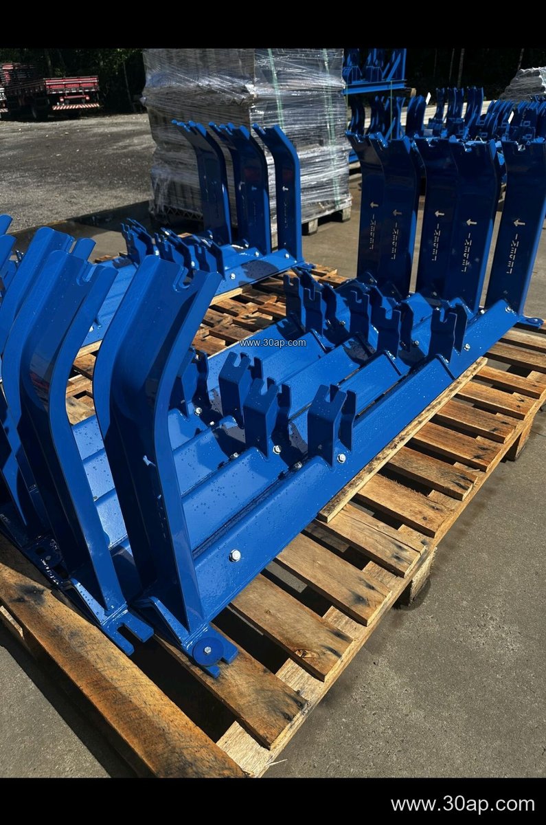
Most units are fabricated from angle steel, channel steel, or folded steel plate. The frame is welded or bolted, then drilled to suit the mounting hole spacing of the associated idler roller. Because hole spacing and crossbeam length change with belt width and trough angle, these dimensions are determined by design rather than fixed by a single rule.
Typical configurations include:
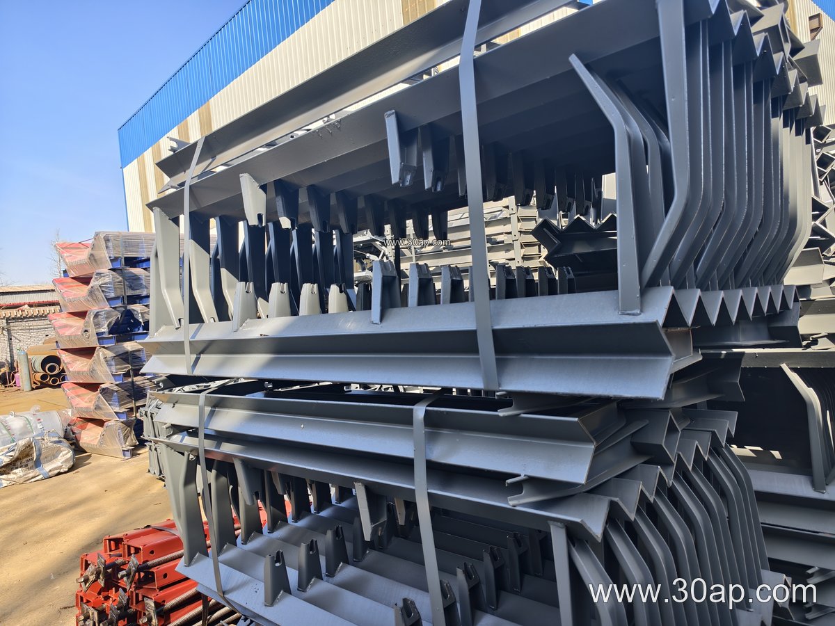
- Three-roll trough brackets for the carrying side at the load point
- Two-roll or V-return brackets used where the return strand also needs cushioning
- Adjustable brackets that allow the trough angle to be set between common values such as 20, 30, 35, and 45 degrees
- Fixed brackets welded to the stringer for a single, permanent angle
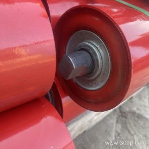
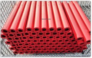
Impact rollers are commonly fitted in diameters of Ø89, Ø108, Ø133, Ø159, and Ø194 mm. A bracket for B800 belt at 35 degrees with Ø108 rollers is a familiar combination, but the same belt width may also run different roller diameters and angles depending on load and belt tension. On wider installations such as B1400 or B1600, the bracket becomes a heavier fabricated assembly with reinforced gussets.
Where It Fits in the Plant
The load zone is the obvious location, but the same bracket family appears at transfer towers and at the discharge of crushers. In an iron ore or limestone operation, a transfer chute may drop material two or three meters, and the impact station is placed just downstream of the skirted section. In a power plant coal handling system, the bracket sits under the belt at the tripper or bunker feed point.
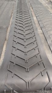
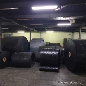
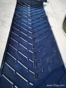
The bracket works alongside the belt itself. A heavy-duty rubber conveyor belt or an abrasion resistant conveyor belt tolerates impact better when the rollers beneath it are properly supported and free to rotate. Where the material is hot, a heat resistant conveyor belt still needs a bracket that will not distort under thermal cycling. In underground coal mining, a flame retardant conveyor belt is paired with brackets that meet the same fire-safety expectations for the installation.
Selection Points for Buyers
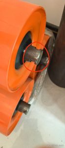
Buyers should start with the belt width and the required trough angle, then confirm the roller diameter and the mounting hole pattern. A bracket that does not match the roller shaft and frame holes will not seat correctly, no matter how strong it is.
| Parameter | Common Range | Note |
|---|---|---|
| Belt width | B500 to B2200 | Frame length follows width |
| Trough angle | 20, 30, 35, 45 degrees | Adjustable versions cover several |
| Roller diameter | Ø89 to Ø194 mm | Match to load and belt speed |
| Material | Angle, channel, folded plate | Thickness by design |
Also check the available drop height and lump size. A bracket that is adequate for a fine aggregate stream may be undersized for run-of-mine ore. Where the conveyor carries a steel cord conveyor belt or an EP conveyor belt under high tension, the impact station should be positioned so that the belt is fully supported before it takes the load.
Maintenance and Field Notes
Inspect the bracket whenever impact rollers are replaced. Bent crossbeams, elongated bolt holes, and cracked welds are signs that the load zone is overloaded or that material is building up. Keeping the skirt rubber clear and the chute centered reduces side loading on the bracket. For a fabric core conveyor belt or a multi-ply fabric core conveyor belt, a worn impact station often shows up first as cover abrasion or as a ripple near the loading point.
Replacement brackets should be checked against the existing stringer spacing and the roller end configuration before installation. Where the conveyor runs a pipe conveyor belt or a corrugated sidewall conveyor belt, the load zone geometry differs and the bracket layout should follow the manufacturer’s arrangement.