What a Tail Drive Pulley Does
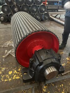
In a belt conveyor, the tail drive pulley is the powered roller at the rear of the system. Unlike a bend pulley or a conventional tail pulley that merely redirects the belt, this component combines the return‑end position with the driving force. It transmits torque from the gearbox or motor to the conveyor belt, pulling the loaded strand forward. This arrangement is common in underground mining conveyors, quarry transport lines, and some cement plant feed sections where space at the head end is limited or where a dual‑drive configuration improves traction.
Because it sits at the tail, the tail drive pulley often works in dusty, wet, or abrasive conditions. Its design must balance grip, belt tracking, and structural rigidity. A correctly specified unit keeps the belt centered, reduces slip, and extends the service life of both the pulley and the belting.
Construction and Key Features
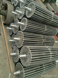
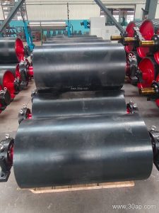
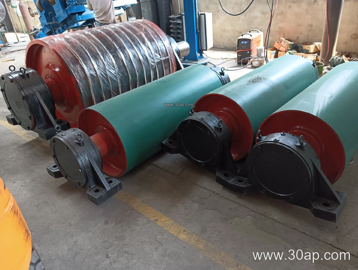
Most tail drive pulleys are built from a welded steel drum with a machined hub and shaft. The shell is typically thicker than that of a non‑drive tail pulley to handle the torque and radial loads. Common surface options include plain steel, rubber lagging (cold‑bonded or hot‑vulcanized), diamond grooving, and ceramic tiles. Lagging improves friction between the drum and the belt, which is especially important when the conveyor carries heavy loads or operates on an incline.
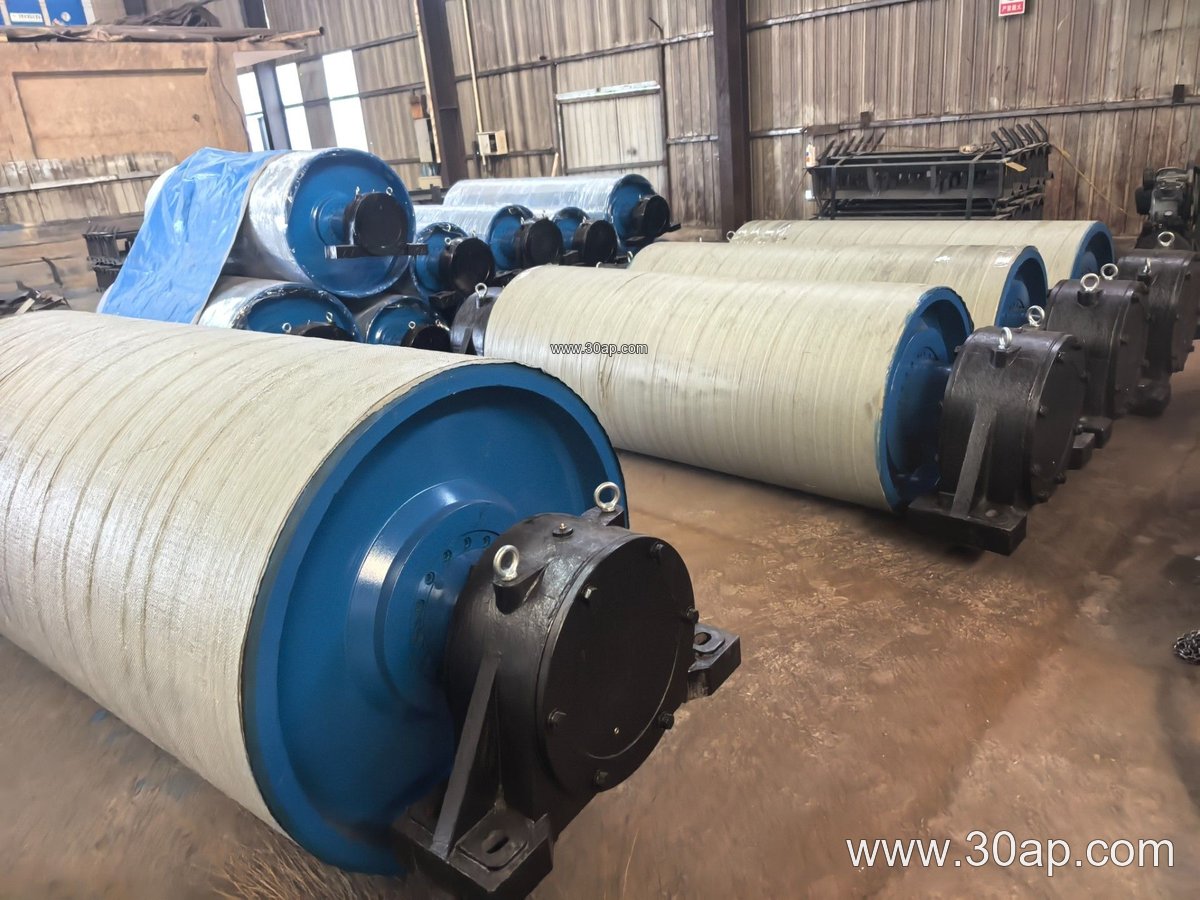
Shaft diameter is selected based on torque and bearing load, not simply on belt width. Typical shaft sizes range from Ø50 mm for small units to Ø200 mm for large mining conveyors. The pulley face width usually exceeds the belt width by 50–200 mm to allow for belt wander; for example, a B800 belt might run on a pulley with a 950 mm face, while a B1200 system could use a 1400 mm face. Diameters commonly fall between Ø200 mm and Ø1800 mm, with the final choice depending on belt speed, wrap angle, and required traction.
Bearing housings are often split for easy maintenance, and the shaft may be keyed or shrink‑fitted to the hub. Some designs include a built‑in brake disc or a torque‑arm mount for the gearbox. In dusty applications such as a coal mining conveyor, labyrinth seals or grease‑purged bearings help keep contaminants out.
Where It Fits in the Conveyor Layout
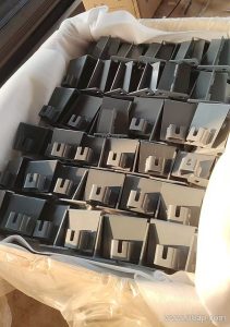
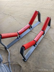
A tail drive pulley is frequently used in long overland conveyors, underground coal mining systems, and quarry conveyor lines where the material is loaded at the tail. It can also appear in cement plant clinker transport, power plant coal handling, and port bulk terminals. In these settings, the pulley works together with idler rollers, conveyor brackets, and the belt itself to maintain a stable path.
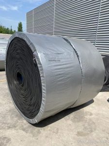
For example, in a stone crushing plant, a tail drive pulley may pull a heavy‑duty mining conveyor belt loaded with aggregate. The same pulley type can be found in a fertilizer granulation line, where a rubber conveyor belt with oil‑resistant properties is used. The key is that the tail position allows the drive to be placed away from the discharge point, which can simplify structural design and reduce material buildup on the drive components.
Selection and Maintenance Notes
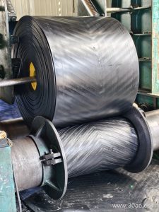
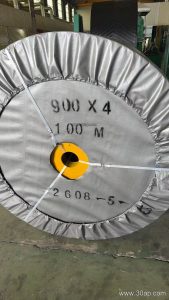
Buyers should consider belt width, belt type, expected tension, and environmental conditions. A pipe conveyor belt or a corrugated sidewall belt may require a different pulley face and lagging pattern than a flat EP conveyor belt. For high‑abrasion service, such as iron ore or copper ore handling, ceramic lagging can outlast plain rubber. In cold climates, a cold‑resistant conveyor belt may be paired with a pulley that has been balanced for low‑temperature operation.
Routine checks include lagging wear, bolt tightness, bearing temperature, and belt tracking. Misalignment often shows up as uneven wear on one side of the pulley face. Keeping the pulley clean and the lagging free of embedded material helps maintain friction and prevents belt slip.
Common Reference Dimensions
The following table lists typical combinations seen in industrial applications. These are reference values, not fixed rules; final dimensions are determined by the conveyor designer.
| Belt Width | Typical Pulley Face Width | Common Diameter Range | Typical Shaft Diameter |
|---|---|---|---|
| B500 | 600 mm | Ø250–Ø400 | Ø60–Ø80 |
| B650 | 750 mm | Ø315–Ø500 | Ø70–Ø90 |
| B800 | 950 mm | Ø400–Ø630 | Ø80–Ø100 |
| B1000 | 1150 mm | Ø500–Ø800 | Ø90–Ø120 |
| B1200 | 1400 mm | Ø630–Ø1000 | Ø100–Ø140 |
| B1400 | 1600 mm | Ø800–Ø1250 | Ø120–Ø160 |
| B1600 | 1800 mm | Ø1000–Ø1400 | Ø140–Ø180 |
For more information on matching pulleys with conveyor belts, idler rollers, and brackets, visit our site at www.example.com/conveyor-pulley. Our team can help you review tail drive pulley options for your specific bulk material handling project.