What a Conveyor Bracket Assembly Does
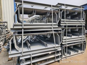
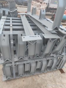
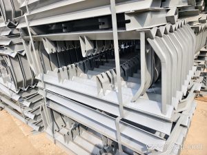
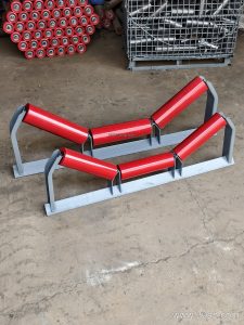
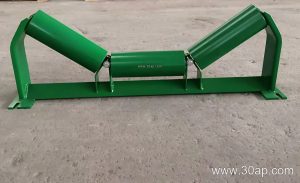
A conveyor bracket assembly is the structural interface that holds idler rollers in the correct position along a conveyor frame. It is not a single piece of hardware but a complete unit—typically a crossbeam or frame section fitted with mounting plates, slots, and fasteners—that supports the carrying side or return side of a conveyor belt. In a quarry, cement plant, or coal handling system, these assemblies keep the belt profile stable, reduce spillage, and help maintain proper belt tracking.
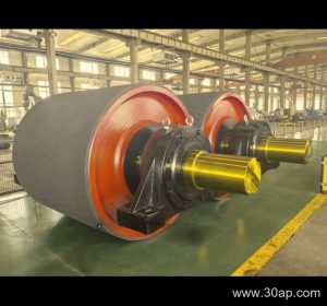
While the term is often shortened to conveyor bracket, the assembly includes the bracket body, mounting holes, and often adjustable features for trough angle or roller spacing. It works together with conveyor pulley, conveyor belt, and idler roller to form the load-bearing section of the conveyor. Without a properly specified bracket assembly, even a high-quality EP conveyor belt or steel cord conveyor belt cannot run smoothly.
Construction and Common Configurations
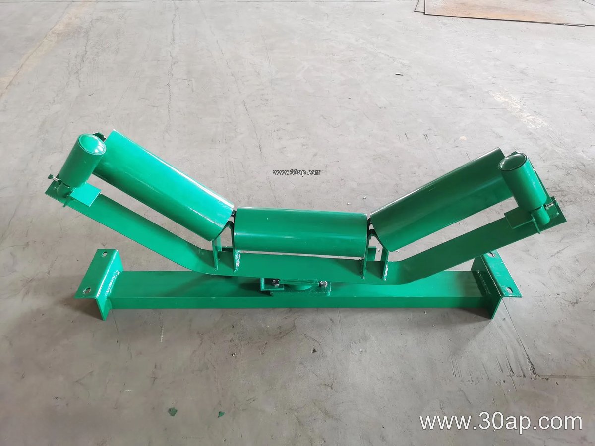
Most assemblies are fabricated from angle steel, channel steel, or folded steel plate. The material thickness and coating depend on the duty level—heavier gauges are common in primary crushing and bulk material handling, while lighter sections may suit auxiliary conveyors. The assembly may be fixed or adjustable. Adjustable types allow the trough angle to be set between common values such as 20, 30, 35, or 45 degrees, which helps optimize material containment for different belt widths and loads.
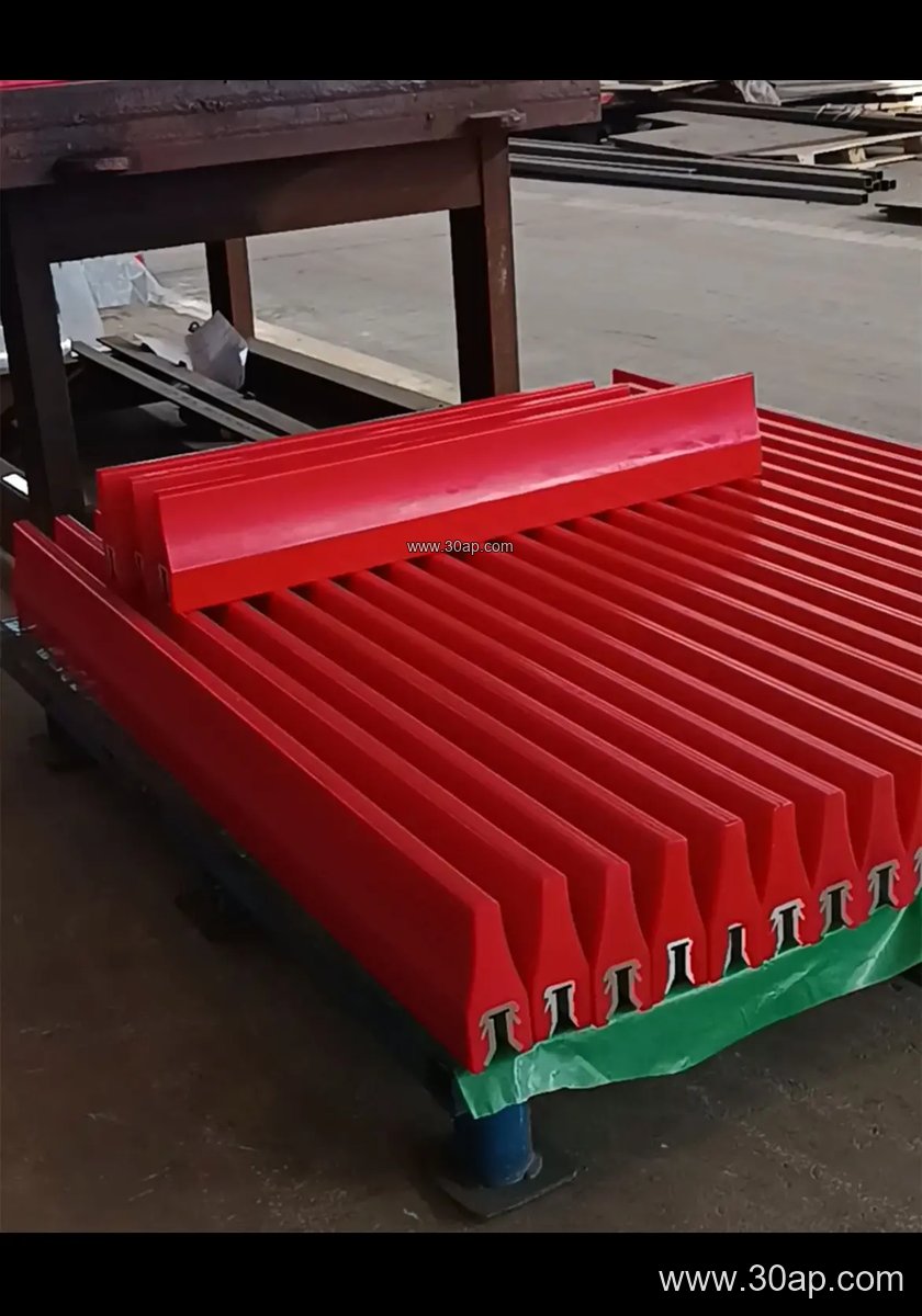
Common bracket types include troughing brackets for the carrying side, return brackets for the lower run, impact brackets for loading zones, and self-aligning brackets for tracking control. A transition bracket is used near pulleys to guide the belt from a flat to a troughed profile. Each type is designed for a specific location, and they are not interchangeable with drive, tail, or bend pulleys.
Typical Reference Parameters
The following values are for reference only and should be confirmed against the actual conveyor design. Belt width, trough angle, and roller diameter are matched by the engineer, not by a fixed rule.
| Belt Width (B) | Common Trough Angle | Common Roller Diameter |
|---|---|---|
| B500 | 20–30 degrees | Ø89 |
| B650 | 30 degrees | Ø89–Ø108 |
| B800 | 30–35 degrees | Ø108 |
| B1000 | 35 degrees | Ø108–Ø133 |
| B1200 | 35–45 degrees | Ø133 |
| B1400 | 35–45 degrees | Ø133–Ø159 |
| B1600 | 35–45 degrees | Ø159 |
| B1800 | 35–45 degrees | Ø159–Ø194 |
| B2000 | 35–45 degrees | Ø194 |
Mounting hole spacing and crossbeam length vary with belt width and trough angle. A B800 assembly with 35-degree trough and Ø108 rollers is a common combination, but it is not the only valid one. Similarly, a B1200 conveyor might use 45-degree troughing with Ø133 rollers in a cement plant, while a B650 assembly with 30-degree trough and Ø89 rollers could suit a smaller aggregate line.
Where These Assemblies Are Used
Conveyor bracket assemblies appear wherever bulk materials move on a belt. In a limestone quarry or stone crushing line, impact brackets and troughing brackets support the belt under heavy rock loads. In a coal mining operation, flame retardant conveyor belt and anti-static conveyor belt often run on robust bracket assemblies designed for dusty, wet conditions. Power plant coal handling, port ship loading, and fertilizer or grain silo systems also rely on these components for stable belt support.
They are equally relevant for heat resistant conveyor belt in a sinter plant or cement kiln area, and for oil resistant conveyor belt in recycling or chemical environments. The bracket assembly itself does not contact the material, but its alignment and strength directly affect belt life and energy consumption.
Buyer Checklist for Conveyor Bracket Assembly
- Confirm belt width (for example B800, B1000, B1200) and the required trough angle range.
- Match roller diameter and bracket mounting dimensions to the idler roller selection.
- Choose fixed or adjustable brackets based on whether the trough angle may need future changes.
- Specify material and surface treatment for the environment—dust, moisture, or corrosive atmosphere.
- Check compatibility with the conveyor pulley layout, especially transition and impact zones.
- Review the assembly drawing for hole spacing and crossbeam length rather than assuming a standard size.
For anyone specifying a conveyor bracket assembly, the key is to treat it as part of the whole conveyor system—alongside conveyor belt, idler roller, and conveyor pulley—rather than as an isolated part. At www.example.com/conveyor-bracket-assembly you can find more reference information, and related components such as rubber conveyor belt and fabric core conveyor belt are often selected in the same design phase.