What a Conveyor Leg Does
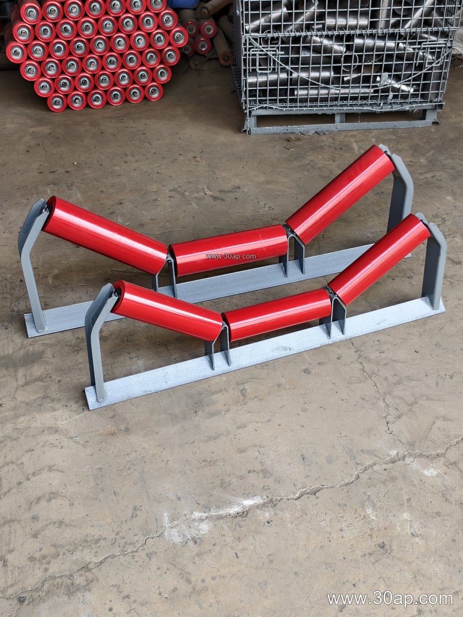
A conveyor leg is the vertical support that carries the weight of the idler frames, the belt, and the material being moved. On a typical troughed conveyor, the leg rises from a concrete plinth or steel base and connects to a crossbeam that holds the idler roller sets. In a quarry or a sand and gravel line, these legs are often the most visible part of the structure, spaced at regular intervals along the entire run. A well-made leg keeps the frame square, holds the chosen trough angle, and resists vibration from heavy aggregate or ore.
The same component is also called a conveyor support leg or stand leg. It is not a pulley and should not be confused with a conveyor pulley at the head or tail of the drive. The leg is a structural element; the pulley is a rotating one.
How the Leg Is Built
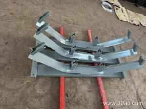
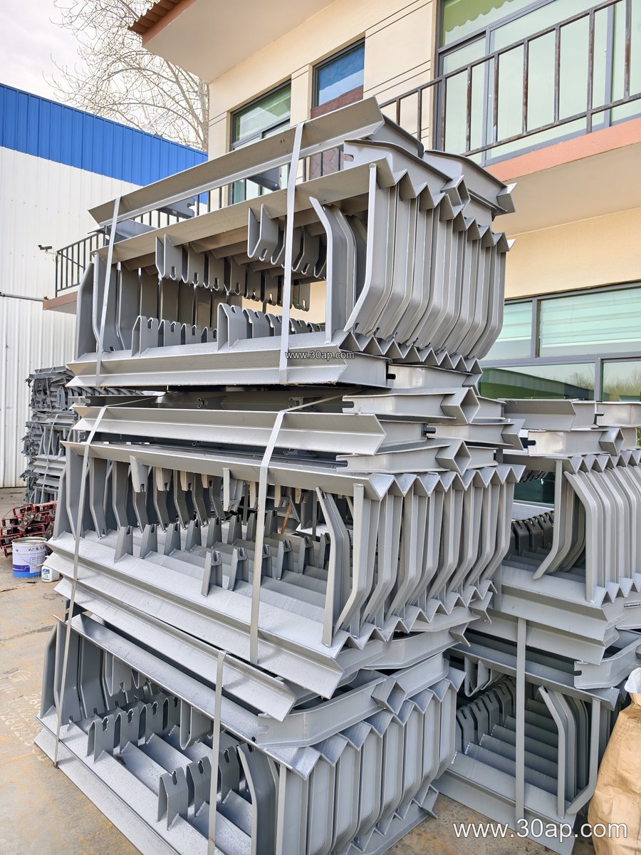
Most legs are fabricated from angle steel, channel steel, or folded steel plate. The top of the leg usually carries a mounting plate or slotted holes so the crossbeam and bracket can be bolted on site. Height is set by design, and adjustable versions use a telescopic section or shim plates to fine-tune the frame line. Hot-dip galvanizing or painting is common for outdoor installations such as a power plant coal yard or a port stockyard.
A leg must match the frame it supports. The hole spacing and crossbeam length change with belt width and trough angle, so these are determined per project rather than fixed numbers.
Where Conveyor Legs Are Used
These supports appear wherever a belt conveyor runs above ground. In a limestone mine or crushing and screening plant, legs carry the inclined and horizontal sections that feed a crusher conveyor belt. In a cement plant they support clinker and raw meal lines. In a coal washing plant, legs hold the frames that keep a flame retardant conveyor belt running straight. The structure must suit the duty: a heavy-duty mining conveyor belt loaded with iron ore demands a stiffer leg and a wider base than a light package line.
Legs also work together with the rest of the frame. A misaligned leg will twist the idler roller set, which in turn causes belt tracking problems and edge wear.
Common Reference Data
The table below lists typical values used in design discussions. Treat them as reference, not as fixed combinations or supply promises.
| Item | Common Reference Values |
|---|---|
| Belt width | B500, B650, B800, B1000, B1200, B1400, B1600, B1800, B2000 |
| Trough angle | 20°, 30°, 35°, 45° (adjustable legs allow changes) |
| Idler diameter | Ø89, Ø108, Ø133, Ø159, Ø194 |
| Material | Angle steel, channel steel, folded plate |
| Typical combinations | B800 / 35° / Ø108; B1200 / 45° / Ø133; B650 / 30° / Ø89 |
No single belt width is tied to one trough angle or one roller diameter. A B1000 frame may run at 30° or 35° depending on the material and the required capacity.
What Buyers Should Check
- Frame compatibility: Confirm the leg matches the crossbeam, bracket, and idler roller set already specified.
- Load and spacing: Leg spacing and section size follow the belt load, the material bulk density, and the site wind or seismic conditions.
- Adjustability: Adjustable legs help correct small height differences on uneven ground; fixed legs are simpler and stiffer.
- Surface protection: Outdoor sites such as a port or power plant benefit from galvanized or coated legs.
- Belt interaction: The leg sets the frame height and angle, which affects how the conveyor belt sits on the rollers and how the skirted conveyor belt or corrugated sidewall conveyor belt clears the structure.
For a large project, the leg drawing should be reviewed together with the pulley layout and the idler schedule. A leg that is correct on paper but wrong on the base plate will cost time during installation.
Maintenance Notes
Inspect legs for loose bolts, corrosion at the base, and bent sections after impact events. A slight lean can shift the trough angle and load the rollers unevenly. Keeping the frame line true protects the belt, the idler roller, and the conveyor bracket assembly alike.