What Conveyor Pulley Lagging Does on a Belt Conveyor
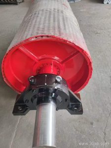
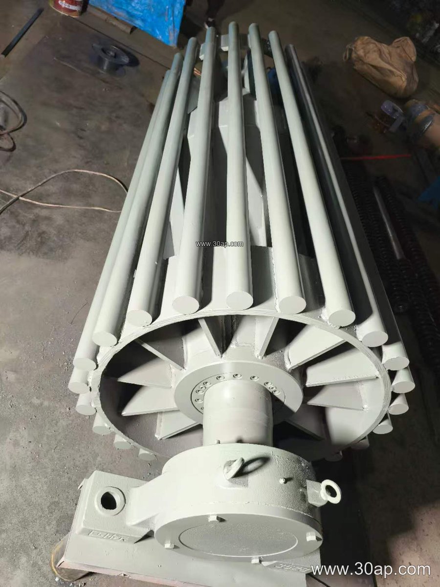
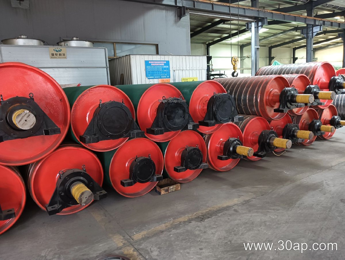
Conveyor pulley lagging is the rubber or ceramic layer bonded to the outside of a conveyor pulley shell where the conveyor belt makes contact. Its job is simple to describe but important in practice: it raises friction between the pulley and the belt, protects the steel shell from wear, and helps keep the belt tracking steadily. In a quarry, a coal preparation plant, or a power plant coal handling line, a drive pulley without reliable lagging will slip under load, especially in wet or dusty conditions. The lagging is therefore a wear part with a direct effect on starting, stopping, and belt life.
The product is often called pulley lagging, drum lagging, or pulley rubber lagging. Those names refer to the same item. Drive pulleys, tail pulleys, and bend pulleys are different positions on the conveyor and should not be treated as interchangeable, because the demands on each position differ.
How the Lagging Is Built and Fitted
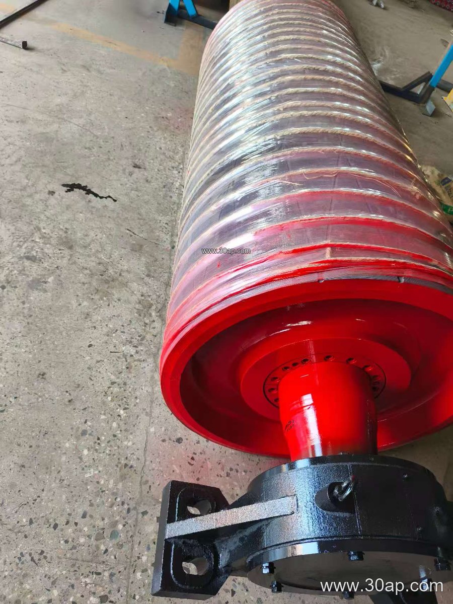
Most lagging starts as a rubber sheet, either plain or with a patterned surface. It is attached to the pulley shell in one of three common ways: hot vulcanized bonding, cold bonded adhesive, or cast-on rubber applied directly to the drum. Ceramic tiles embedded in a rubber matrix are used where abrasion is severe and extra grip is needed. The choice of bonding method affects cure time, workshop requirements, and how easily the lagging can be replaced later.
Typical surface forms include plain sheet, diamond grooved, herringbone, and ceramic. Grooved patterns help water and fine dust escape from the contact zone. Common lagging thicknesses are 8, 10, 12, 15, and 20 mm, selected according to pulley diameter, belt tension, and duty. A thicker layer gives more wear allowance but also changes the effective pulley diameter, so the belt path and take-up should be checked when specifying it.
Where Lagging Matters Most
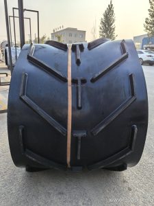
The drive pulley, sometimes called the head pulley when it also discharges material, carries the highest tangential load, so it usually needs the strongest grip. Tail pulleys and bend pulleys see different conditions and may use thinner or plain lagging. In an iron ore or copper ore operation, abrasive fines attack the shell constantly; in a cement plant clinker line, heat and sharp material add another stress. A steel cord conveyor belt carrying heavy ore loads needs dependable friction at the drive, while a fabric core conveyor belt on a shorter aggregate line may be more forgiving.
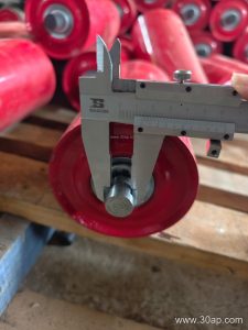
Lagging also interacts with the rest of the conveyor. Poorly maintained idler rollers or a misaligned conveyor bracket can cause belt wander that no amount of lagging will fix. The lagging should be specified together with the belt, the pulley, and the supporting structure, not in isolation.
Common Reference Dimensions
The table below gives typical reference values. They are guidance for discussion, not fixed supply promises, and the final combination is set by the conveyor design.
| Item | Typical reference values |
|---|---|
| Belt width | B400, B500, B650, B800, B1000, B1200, B1400, B1600, B1800, B2000 |
| Pulley diameter | Ø200, Ø250, Ø315, Ø400, Ø500, Ø630, Ø800, Ø1000, Ø1250, Ø1400 |
| Lagging thickness | 8, 10, 12, 15, 20 mm |
| Surface form | Plain, diamond, herringbone, ceramic |
| Shaft diameter | Ø50 to Ø200, determined by torque and load |
Examples such as B800 x Ø500 or B1200 x Ø1000 appear in real projects, but no single belt width is tied to one pulley diameter. Shaft size follows the calculated torque and bearing load rather than belt width alone.
Buyer Checklist Before Ordering
- Confirm the pulley position: drive, tail, tension, or bend, since each has different friction and wear requirements.
- State the belt type and duty, for example an abrasion resistant conveyor belt or a heat resistant conveyor belt, so the rubber compound can be matched.
- Give the pulley shell diameter and face width, and check that the new lagging thickness keeps the belt path correct.
- Choose the surface pattern based on whether the main problem is slip, water, dust, or abrasion.
- Ask how the lagging is bonded and how it can be replaced in the field.
For operators in mining, steel plants, ports, and sand and gravel lines, a small investment in the right lagging often pays back through fewer belt stoppages. Matching the lagging to the pulley position and the conveyed material is the practical starting point.