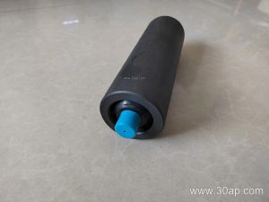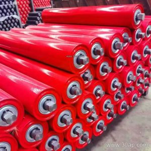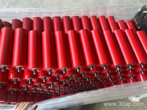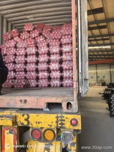
Introduction to the Head Discharge Unit
In heavy bulk material handling applications such as a busy cement plant熟料 line or a large-scale quarry operation, the discharge zone demands robust mechanical components. At the terminal point of the material flow, the Belt Conveyor Head Pulley serves as the primary mechanism that transmits rotational force from the drive motor to the main 输送带, propelling it forward while releasing the carried burden into downstream chutes. Unlike a tail unit or standard 滚筒 variants, this discharge component operates under peak tension and high frictional stress.
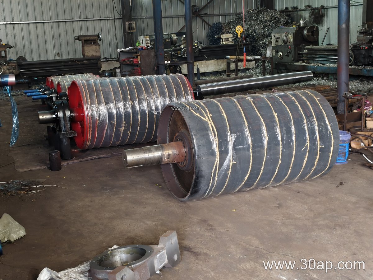
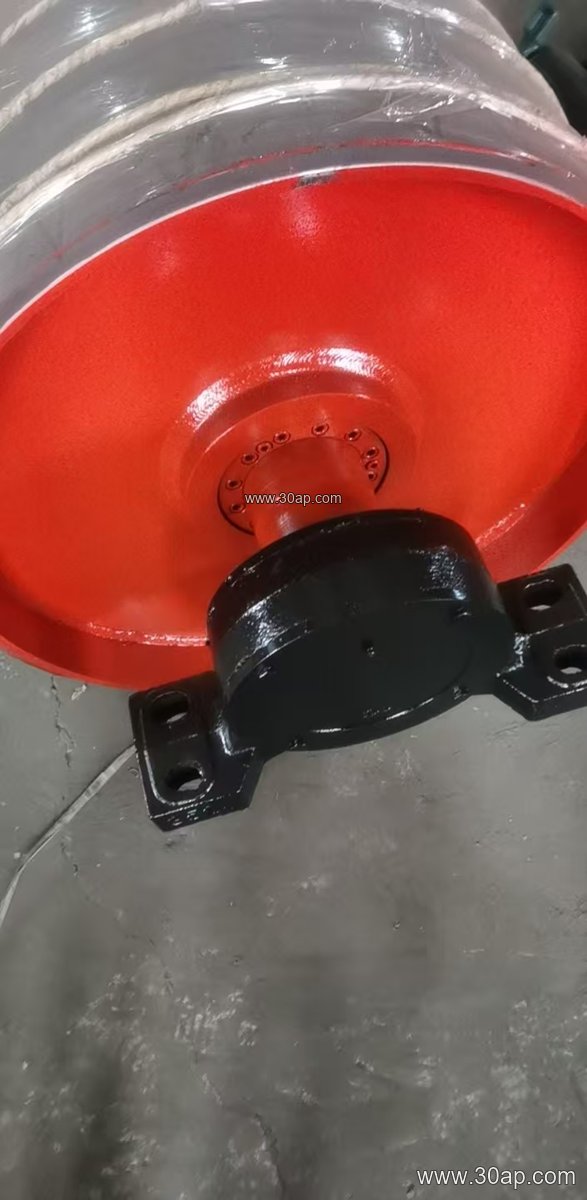
Structural Composition and Surface Lagging Options
The assembly typically features a heavy-duty steel shell, welded end discs, and a through-shaft supported by heavy-load bearings mounted on rigid steel 支架. To improve traction and prevent slippage between the shell and the moving 输送机托辊-supported belt, the cylindrical surface is frequently treated with protective cladding. Operators can select from several surface configurations depending on moisture levels and environmental wear factors:
- Plain bare steel surface for light, dry utility duties.
- Cold vulcanized or hot vulcanized rubber lagging.
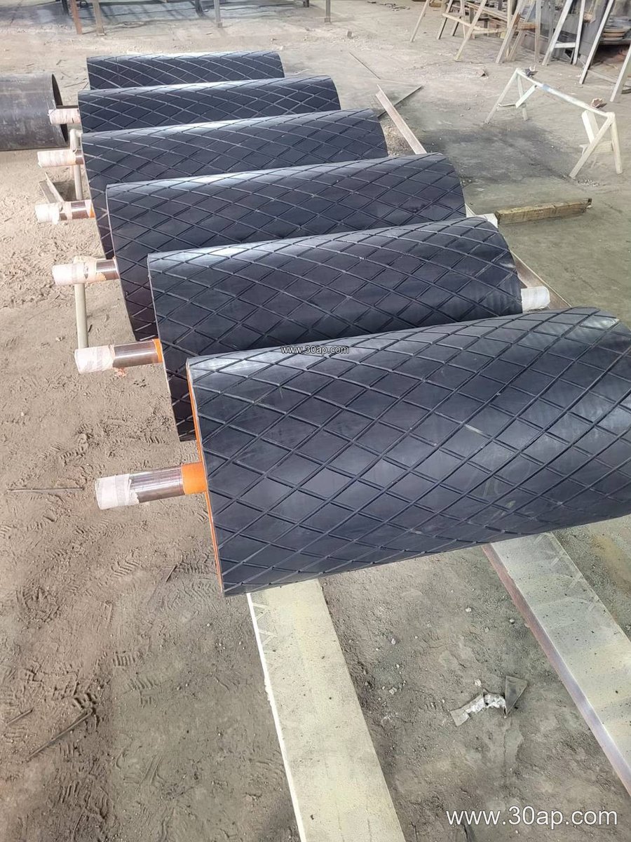
- Diamond or herringbone patterned grooved rubber for enhanced water drainage.
- Ceramic-tiled lagging for high-abrasion ore and aggregate handling.
Dimensional Range and Engineering Reference Data
Selecting the correct unit size requires evaluating belt tension, wrap angles, and torque requirements rather than relying on a single fixed rule. Standard design practices utilize proportional pairings between belt width and shell diameter, often paired alongside heavy 托辊 arrays to maintain trough geometry. Below is a reference chart outlining common engineering parameters used across industrial fabrication layouts:
| Nominal Belt Width | Typical Shell Diameter | Approximate Shell Width | Common Shaft Diameter |
|---|---|---|---|
| B650 | Ø400, Ø500 | 750 mm | Ø70, Ø80, Ø90 |
| B800 | Ø500, Ø630, Ø800 | 950 mm | Ø90, Ø100, Ø120 |
| B1000 | Ø630, Ø800, Ø1000 | 1150 mm | Ø120, Ø140, Ø160 |
| B1200 | Ø800, Ø1000, Ø1250 | 1400 mm | Ø140, Ø160, Ø180 |
| B1400 | Ø1000, Ø1250, Ø1400 | 1600 mm | Ø160, Ø180, Ø200 |
Operational Maintenance in Severe Environments
In facilities handling abrasive limestone, clinker, or run-of-mine ore, maintenance teams must inspect the rubber lagging thickness—commonly ranging from 8 mm to 20 mm—on a regular schedule. Uneven wear or material buildup can cause belt misttracking, placing undue stress on the rotating shaft and bearing housings. Keeping the shell clean and verifying alignment guarantees prolonged service life and minimizes unexpected downtime in continuous processing facilities.