What the Assembly Does
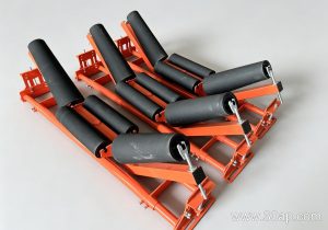
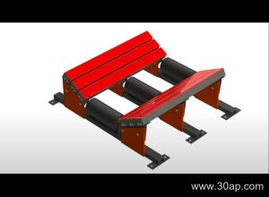
A conveyor bracket assembly is the structural link between the idler roller and the conveyor frame. It holds each roller at the correct height, angle and spacing so the belt keeps its profile under load. Without a stable bracket, a troughing roll can drift out of alignment, the belt edge starts to run off, and spillage follows. The assembly also sets the transition geometry where the belt changes from flat at the tail pulley to troughed through the carrying run.
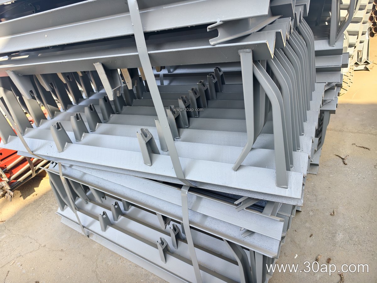
Fabricators usually build these units from angle steel, channel steel or folded plate, then weld or bolt the roller seats into position. A complete assembly may include the cross beam, mounting feet, roller cradles, and adjusting slots. Surface treatment matters in dusty plants, so hot-dip galvanizing or a heavy paint system is common in a cement plant conveyor or a wet coal preparation house.
Common Configurations
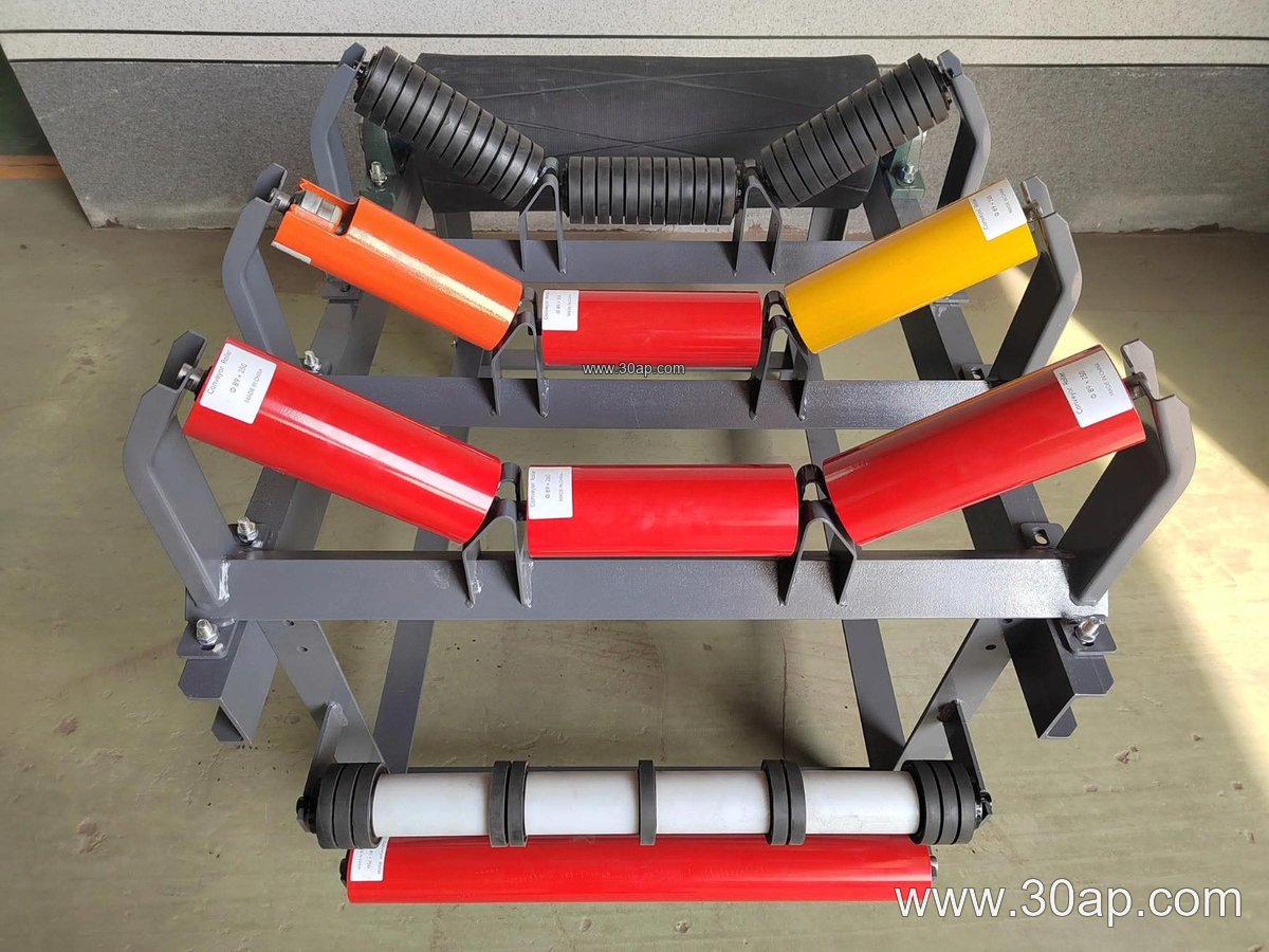
Bracket families follow the belt line they serve. Carrying-side units are usually built as fixed or adjustable troughing brackets; return-side units are flatter and often carry a single roller or a V-shaped pair. Adjustable designs allow the trough angle to be set on site, which helps when a conveyor handles several products or when the belt needs fine tuning after installation.
- Troughing bracket, fixed or adjustable, for the carrying run
- Transition bracket at the tail and head areas
- Return bracket and V-return bracket under the belt
- Impact bracket with cushion rollers below the loading point
- Self-aligning bracket for belts that tend to wander
- Suspended bracket for light, temporary or mobile frames
Each of these is a distinct subtype with its own geometry. A return bracket is not a substitute for a troughing bracket, and the choice should follow the duty point, not convenience.
Matching Belt Width, Trough Angle and Roller Diameter
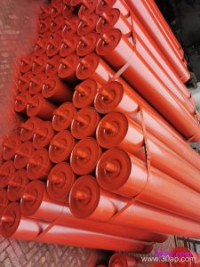
Bracket dimensions are driven by belt width, trough angle and roller diameter. Common belt widths run from B500 up to B2200, trough angles are typically 20, 30, 35 or 45 degrees, and roller diameters include Ø89, Ø108, Ø133, Ø159 and Ø194. The table below shows typical reference combinations; it is not a fixed rule, because one belt width can work with more than one trough angle or roller size depending on capacity and material.
| Belt width | Typical trough angle | Typical roller diameter | Typical use |
|---|---|---|---|
| B500 | 20–30 degrees | Ø89 | Light aggregate, small transfer lines |
| B650 | 30 degrees | Ø89–Ø108 | Sand and gravel, fertilizer handling |
| B800 | 35 degrees | Ø108 | Crushing and screening circuits |
| B1000 | 35–45 degrees | Ø108–Ø133 | Coal washing, power plant coal feed |
| B1200 | 45 degrees | Ø133 | Iron ore, limestone, port loading |
| B1400 | 35–45 degrees | Ø133–Ø159 | Heavy bulk material lines |
| B1600–B1800 | 35–45 degrees | Ø159–Ø194 | Large tonnage mining and steel plants |
| B2000–B2200 | 35–45 degrees | Ø194 | Wide belts at high capacity terminals |
Installation hole spacing and cross beam length change with width and trough angle, so these should be confirmed from the drawing rather than assumed. A forward-leaning bracket is sometimes set about 1.5 to 2 degrees ahead of the belt direction to help centering, but that detail belongs to the design, not to a universal standard.
Where These Assemblies Are Used
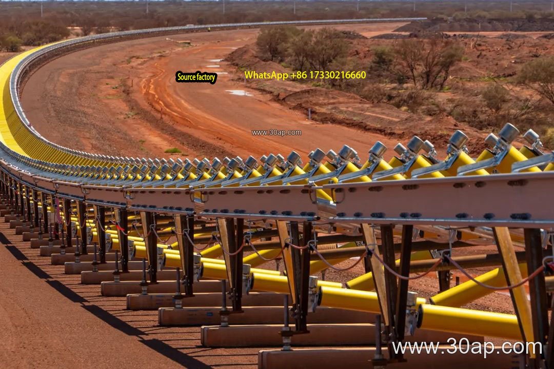
You will find bracket assemblies wherever a belt conveyor carries bulk material. In a limestone quarry they support the primary and secondary transfer belts; in a power plant coal yard they sit under belts fed by stackers and reclaimers. A crusher discharge line often uses impact brackets with cushion rollers to absorb lump shock, while a tunnel spoil conveyor may use suspended units on a lighter frame.
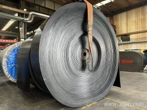
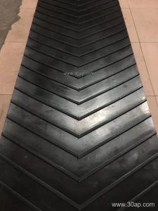
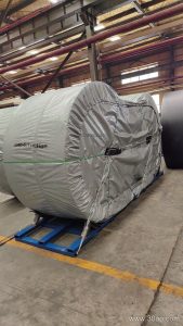
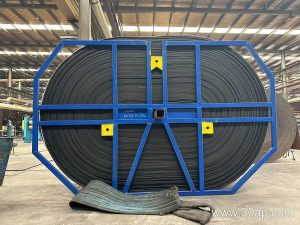
The bracket must suit the belt it carries. A heavy-duty steel cord belt on an ore line needs a stiff cross beam and well-aligned roller seats, while a fabric core belt on a shorter run can use a lighter section. Matching the assembly to the belt type, whether EP, NN or steel cord, keeps the roller contact even and extends cover life.
Buyer Checklist
- Confirm belt width, trough angle and roller diameter together, not separately.
- State whether the unit is fixed or adjustable, and which angle range is needed.
- Ask for the mounting hole pattern and cross beam length on the drawing.
- Check material thickness and surface treatment for the site conditions.
- Confirm whether the bracket is for the carrying run, return run, transition or loading point.
- Review roller seat alignment, since small errors show up as belt tracking problems.
A well-chosen conveyor bracket assembly is a quiet component, but it decides how evenly the belt sits on its rollers and how long the whole line runs without attention.