What a Conveyor Frame Does on a Belt Conveyor
A conveyor frame is the load-bearing structure that holds the idler roller sets, pulleys and belt in correct alignment along the entire run. In a quarry, a coal washing plant or a cement clinker line, the frame carries the weight of the conveyor belt, the material and the rollers, and keeps every component in its designed position. It is not a single part but a system of longitudinal beams, cross members and mounting brackets that together form the conveyor’s backbone.
The frame is usually described by its function and location: a troughing frame carries the upper carrying idlers, while a return frame supports the lower run. Both belong to the same product family but are not interchangeable, and each has its own mounting geometry.
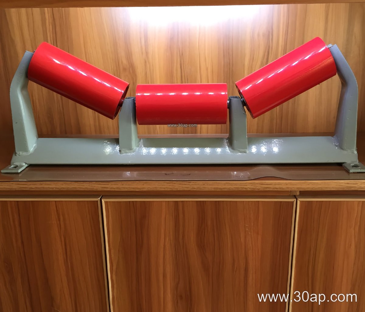
How the Structure Is Built
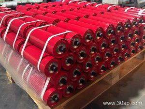
Most frames are fabricated from angle steel, channel steel or folded steel plate, then drilled or punched for mounting holes. The cross beam length, hole spacing and trough angle must match the belt width and the idler diameter used at that station. A typical upper troughing frame at a sand and gravel line might be built for B800 with a 35 degree trough and Ø108 idlers, while a heavy iron ore duty station could use B1200, 45 degree trough and Ø133 rollers. These are common arrangements, not fixed rules — final dimensions are confirmed by design.
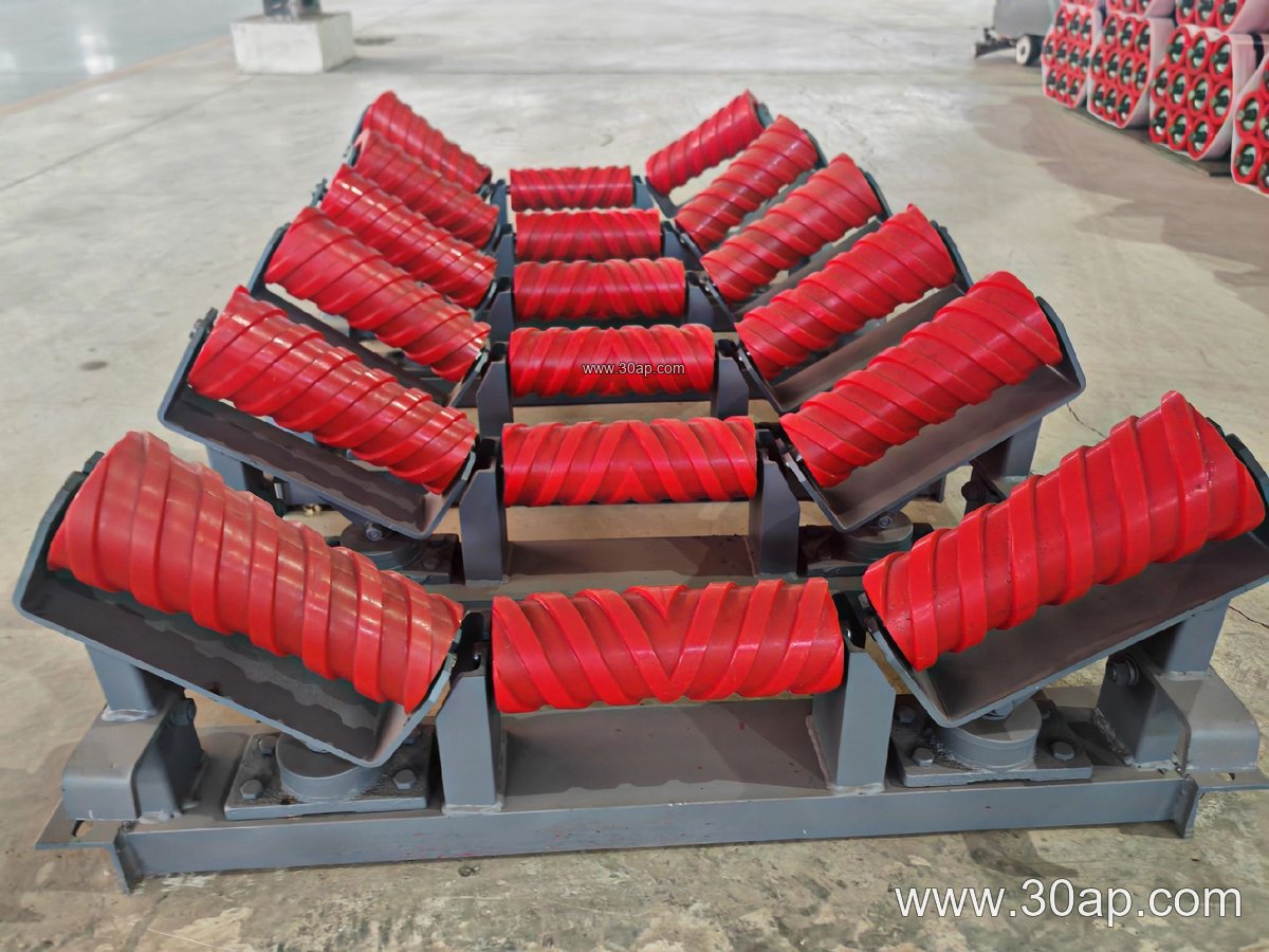
Welded frames are common for fixed installations, while bolted frames simplify transport into tunnels or underground coal mining sections. Surface treatment such as painting or galvanizing is chosen according to the humidity and dust conditions at the site.
Common Frame Types and Reference Dimensions
The table below lists typical frame variants and reference belt width ranges. Values are for orientation only; actual hole spacing and beam length follow the engineering drawing.
| Frame Type | Typical Belt Width | Common Trough Angle | Common Idler Diameter |
|---|---|---|---|
| Upper troughing frame | B500 to B2000 | 20, 30, 35, 45 degrees | Ø89, Ø108, Ø133, Ø159 |
| Transition frame | B650 to B1800 | 20 to 35 degrees | Ø89 to Ø159 |
| Return flat frame | B500 to B2200 | Flat | Ø89 to Ø194 |
| V-return frame | B650 to B1800 | V shape | Ø108 to Ø159 |
| Impact frame | B800 to B1600 | 20 to 35 degrees | Ø108 to Ø159 |
| Self-aligning frame | B500 to B2000 | 20 to 45 degrees | Ø89 to Ø159 |
| Adjustable frame | B500 to B1800 | 20 to 45 degrees | Ø89 to Ø159 |
Trough Angle and Idler Matching
Trough angle influences how much material the belt can carry and how much stress the belt edge sees. A 30 degree trough is a general choice for many bulk materials, while 45 degree troughs are used where capacity matters and the belt is flexible enough. The frame must be built so the idler roller seats sit at the correct angle, and the mounting holes should align with the roller shaft ends.
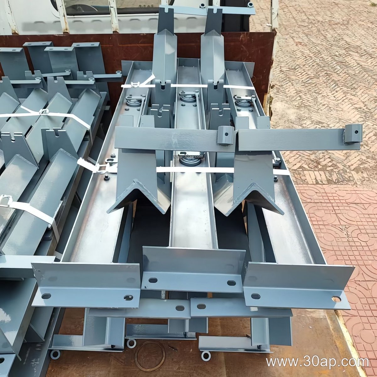
Belt width and roller diameter are matched by design rather than by a single fixed rule. A B650 frame with Ø89 rollers and a B1400 frame with Ø133 rollers are both normal, and intermediate combinations are common. What matters is that the frame, roller and belt are specified together.
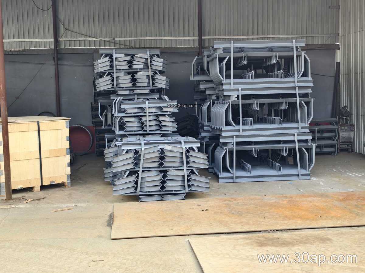
Where Conveyor Frames Are Used
These structures appear wherever bulk material moves continuously. In a limestone mine or aggregate plant, frames support the crusher conveyor and the screening feed lines. In a power plant coal yard, they carry the coal stream from the stockpile to the boiler bunkers. In a port ship loader, frames are designed for high belt tension and long spans. Each site sets its own priorities: dust and moisture resistance in a cement plant, flame retardant considerations in underground coal mining, and abrasion resistance in an iron ore transfer point.
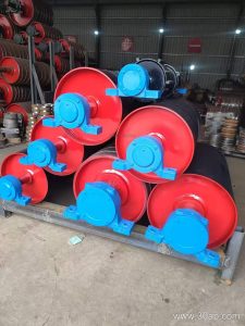
The frame works together with the conveyor pulley at the drive and tail ends and with the conveyor bracket that fixes it to the steel structure. Alignment between frame sections is critical, because a small offset at each joint accumulates over a long conveyor line.
Buyer Checklist Before Ordering
- Confirm belt width and the trough angle required at each station.
- State the idler diameter and shaft end type so mounting holes match.
- Specify fixed or adjustable design if the trough angle may be changed later.
- Describe the environment: dust, moisture, temperature and material abrasiveness.
- Provide the drawing or span between supports, since beam length and hole spacing follow the layout.
- Clarify whether frames ship welded or in bolt-together sections for site access.
When frame, roller and belt are selected as one system, the conveyor runs straighter, the belt tracks better and maintenance intervals lengthen. Buyers who treat the frame as a simple steel part often discover later that small dimensional mismatches cost more than the frame itself.