What a Drive Lagged Pulley Does on a Conveyor
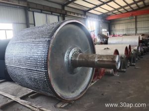
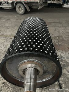
A drive lagged pulley is the powered head pulley that transfers torque from the gearbox to the conveyor belt. Its rubber or ceramic covering, called lagging, raises the friction coefficient between the pulley shell and the belt so that the required traction can be achieved without excessive belt tension. In a quarry, a coal washing plant or a cement clinker line, this component is the point where the entire drive train meets the belt, so its diameter, face width, shaft and surface form all matter.
The same component is often called a lagged drive drum or a rubber-lagged head pulley. These terms describe the same product; they are not interchangeable with a tail pulley or a bend pulley, which serve different positions and duties.
Construction and Surface Options
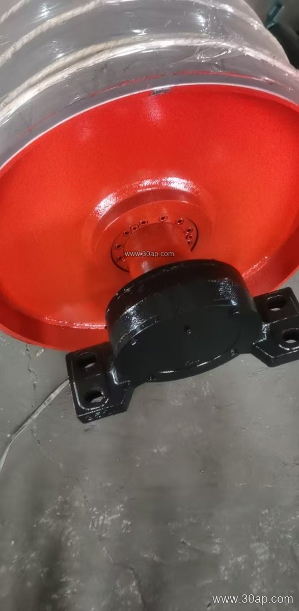
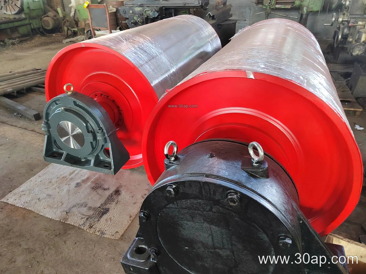
A typical drive lagged pulley consists of a welded steel shell, end discs, a shaft, bearing housings and a lagging layer. The lagging may be applied by hot vulcanisation, cold bonding, casting or ceramic tile bonding, and the surface pattern is chosen to suit the material and the environment.
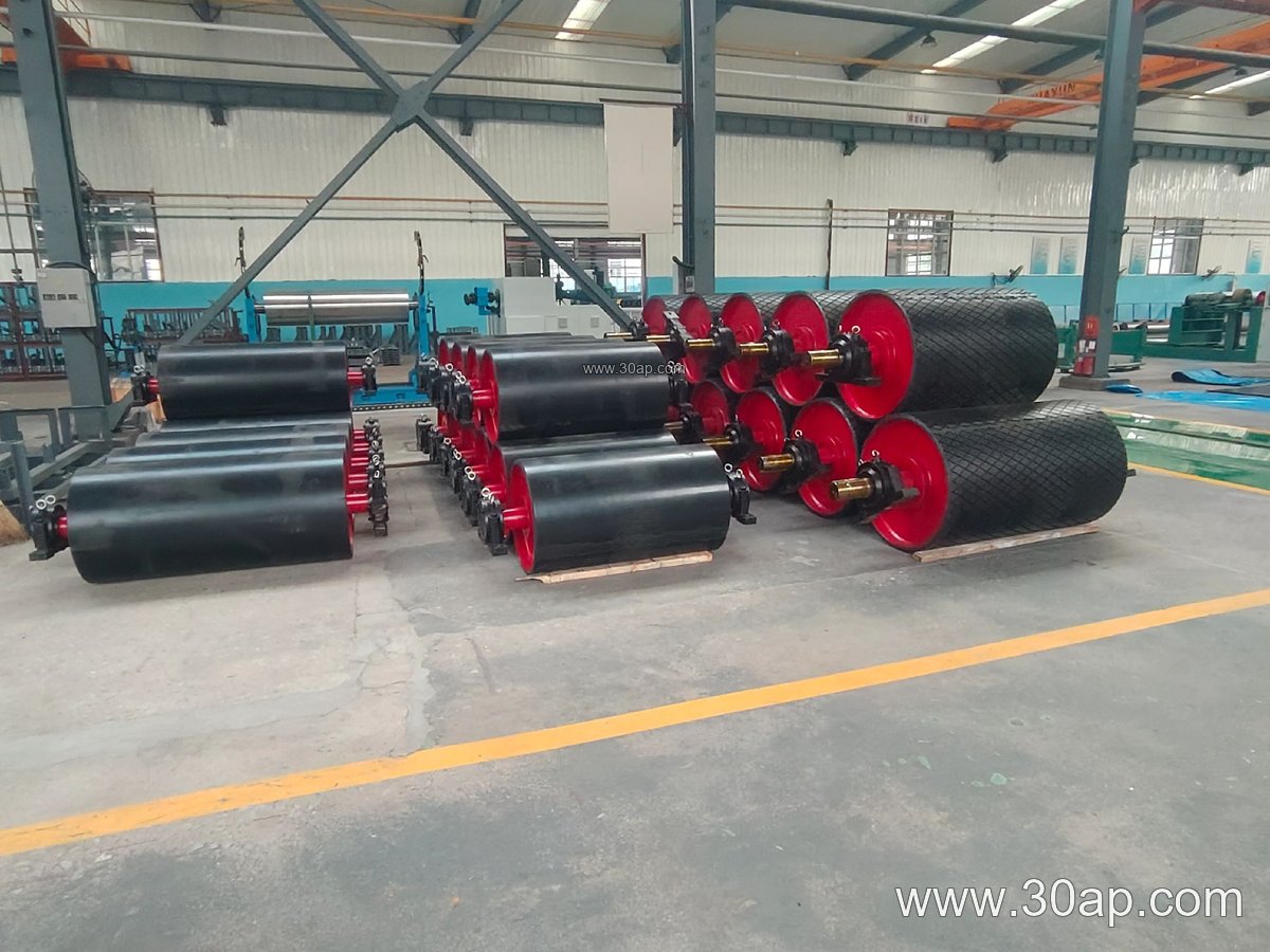
- Flat or plain rubber lagging: general duty, easy cleaning
- Diamond or chevron grooving: improved water and fines evacuation
- Ceramic lagging: high wear resistance in abrasive service
- Thickness commonly 8, 10, 12, 15 or 20 mm, selected by duty
Shell diameter and face width are design choices rather than fixed pairs. A B800 conveyor may use a Ø500 drive pulley, while a B1200 unit in a primary crushing station may run Ø1000 or larger. Shaft diameter is determined by torque and bearing load, not by belt width alone, so a Ø120 shaft on one B1000 drive does not imply the same shaft on every B1000 drive.
Common Reference Dimensions
The following values are typical reference data, not a supply promise. Final dimensions follow the conveyor design.
| Belt width | Typical pulley face width | Example drive pulley combination |
|---|---|---|
| B500 | about 600 mm | B500 × Ø400 |
| B650 | about 750 mm | B650 × Ø500 |
| B800 | about 950 mm | B800 × Ø500 |
| B1000 | about 1150 mm | B1000 × Ø630 |
| B1200 | about 1400 mm | B1200 × Ø1000 |
| B1400 | about 1600 mm | B1400 × Ø800 |
| B1600 | about 1800 mm | B1600 × Ø1000 |
Larger drives in iron ore or port bulk handling may reach Ø1250, Ø1400 or Ø1600, with shaft diameters from Ø100 to Ø200 depending on torque. Lagging thickness and pattern should be confirmed together with the belt cover grade and the ambient conditions.
Where It Is Used
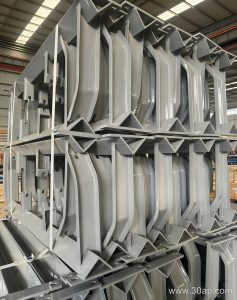
Drive lagged pulleys appear at the head of troughed conveyors in sand and gravel plants, limestone mines, sinter plants and tunnel muck lines. They also drive shuttle and yard conveyors in grain silos and fertiliser storage. In these installations the pulley works with the conveyor belt, conveyor idler rollers and conveyor brackets, and its lagging must match the abrasion and moisture level of the conveyed material.
Position matters. A drive pulley at the head sees the loaded belt and must resist slip under peak starting torque. A bend or snub pulley nearby redirects the belt and is not a substitute for the drive; it is a separate component with its own diameter and bearing selection.
Buyer Checklist
- Confirm the required traction and the belt speed before choosing lagging type and thickness.
- Check that the pulley face width exceeds the belt width by a suitable margin.
- Verify shaft diameter against actual torque and bearing load, not against belt width alone.
- Match lagging pattern to material: diamond for wet fines, ceramic for highly abrasive rock.
- Ask for the balancing grade, bearing type and locking arrangement as part of the technical offer.
- Plan inspection of lagging wear and bolt tightness during scheduled shutdowns.
Correctly specified, a drive lagged pulley keeps starting torque predictable and reduces belt slip, which protects both the conveyor belt and the drive train in demanding mining, cement and power plant service.