What an EP1250 Conveyor Belt Is
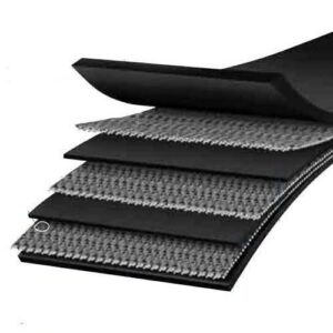
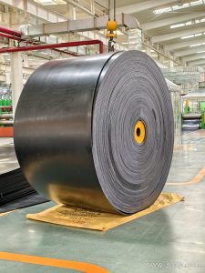
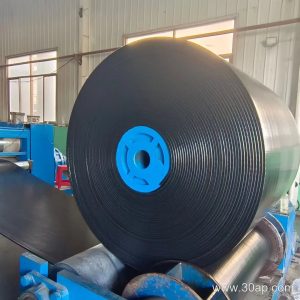
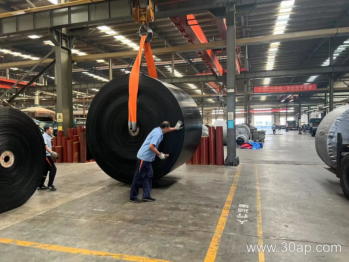
An EP1250 conveyor belt is a multi-ply rubber belt built on a polyester-polyamide (EP) fabric carcass with a nominal tensile strength of 1250 N/mm. The “EP” refers to the warp and weft yarns: polyester in the longitudinal direction and polyamide (nylon) in the transverse direction. This combination gives the belt low elongation under load, good troughability, and strong resistance to impact and fatigue. The EP1250 grade sits in the higher range of common EP belt strengths, above EP1000 and below EP1600, which makes it a frequent choice for main haulage conveyors where long centers and heavy loads are expected.
In everyday language, buyers and maintenance teams may call this a 1250 kN/m EP belt or a polyester nylon conveyor belt with a 1250 strength rating. Those are accurate shorthand for the same product, not a different belt type.
How the Belt Is Constructed
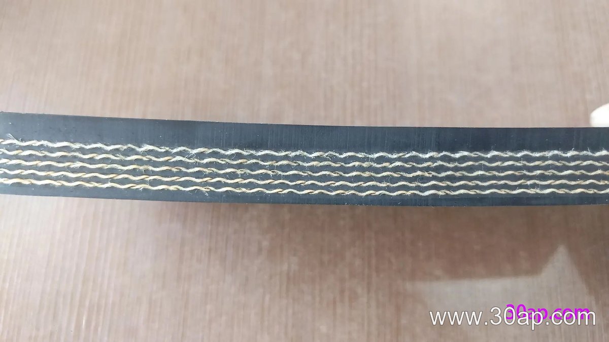
The carcass usually contains two to six fabric plies, with the ply count selected according to the duty and the required safety factor. A typical build includes:
- Top cover rubber, often 4 to 8 mm thick, to resist abrasion, cutting, and the material being carried.
- Bottom cover rubber, commonly 1.5 to 3 mm thick, to protect the pulley side.
- EP fabric plies bonded with skim rubber between layers.
- Edge protection, either cut edges or moulded edges depending on the application.
Cover compounds are chosen for the working environment. Wear-resistant grades suit sharp, dry bulk; heat-resistant grades suit hot clinker or sinter; oil-resistant grades suit grain or recycled material with oil contamination; and flame-retardant or antistatic grades are used in underground or dusty areas where ignition risk must be controlled. The carcass strength of EP1250 remains the same across these variants, but the cover and any surface profile change with the job.
Where It Is Used
This strength class appears in mining, quarrying, cement, steel, port handling, and large bulk terminals. It is common on trunk conveyors that move crushed ore, coal, limestone, aggregates, or sand over long distances and inclines. Because the EP carcass stretches less than a light fabric belt, an EP1250 conveyor belt can handle higher tension and longer take-up travel without frequent re-splicing.
It is also used on stackers, reclaimers, and ship loaders where the belt must start under load. In these places the belt works with a head or drive pulley, a tail pulley, and bend pulleys that route the return strand. These are distinct components with different duties: a drive pulley transmits torque, a tail pulley forms the loading end, and a bend pulley changes direction. They should not be treated as interchangeable names.

Specifying an EP1250 Belt
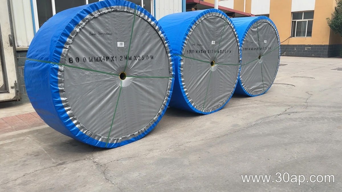
The belt width is not fixed by the strength grade. Common widths include B800, B1000, B1200, B1400, and B1600, and the correct width depends on lump size, capacity, and the troughing idler roller arrangement. A single width does not dictate one pulley diameter; the pulley diameter is selected from the belt construction, ply count, and the required bend radius, not from width alone. Shaft diameter is a separate design decision and should not be guessed from the belt width.
When ordering, provide the following:
- Required belt width and the number of plies.
- Top and bottom cover thickness, for example 5+2 mm or 6+2 mm.
- Cover grade: abrasion, heat, oil, flame retardant, antistatic, or cold resistant.
- Surface form, if needed: smooth, patterned, chevron, or with corrugated sidewalls.
- Splice method, hot vulcanized or mechanical, and whether the belt will be supplied in rolls or as an endless loop.
- Operating tension, trough angle, and the layout of the conveyor pulley and conveyor bracket positions.
For comparison, a steel cord belt offers higher strength in a thinner profile, and a PVC or PVG belt is often chosen for lighter or fire-sensitive duties. Those are different constructions and should not be substituted for an EP1250 belt without a full engineering review.
Installation and Maintenance Notes
Correct alignment at the tail and drive pulleys prevents edge damage. Idler rollers should turn freely and sit square to the belt line. Loading should be centered, with skirt rubber set to avoid trapping material between the belt and the pulley. Keep the belt reasonably clean on the return side; build-up on bend pulleys can cause tracking problems and cover wear.
Inspect the belt regularly for edge fraying, cover gouges, ply separation, and splice wear. A hot vulcanized splice usually gives the longest life on high-tension EP1250 belts, but mechanical fasteners can be acceptable for shorter, lower-duty runs. Track any change in take-up position, because a sudden increase may indicate splice creep or carcass damage.
Buyer Checklist
Before confirming an order, match the belt grade to the actual duty rather than to a catalogue default. Confirm the cover thickness and compound with the material being carried and the ambient temperature. Check that the pulley diameters and conveyor bracket layout suit the selected ply count. Ask for the manufacturer’s data sheet for the specific EP1250 construction, including ply number, cover thickness, and recommended minimum pulley diameter. Values vary between suppliers, so treat any figure as a design input to be verified, not as a universal specification.
What an Aggregate Production Line Idler Does
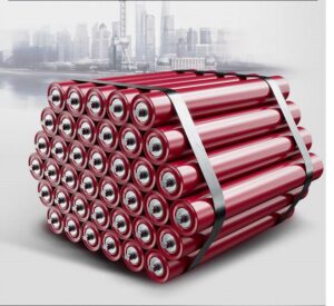
On a crushing and screening site, the belt carries a constant load of rock, sand, and dust. The aggregate production line idler, often simply called a belt idler roller, supports that moving belt and keeps it tracking along the frame. It is not a drive component. It rotates freely under the belt, carrying the weight of the material and the belt itself while reducing friction. Without a reliable set of idlers, the conveyor belt would sag, wear quickly, and spill material at transfer points.
The idler works together with a conveyor pulley at the head and tail, and with a conveyor bracket that holds each roller in position. But the idler is the part that touches the belt along the carrying run. Its job is continuous and repetitive, which is why build quality matters as much as the initial price.
How an Idler Is Built
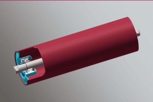
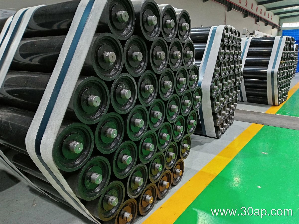
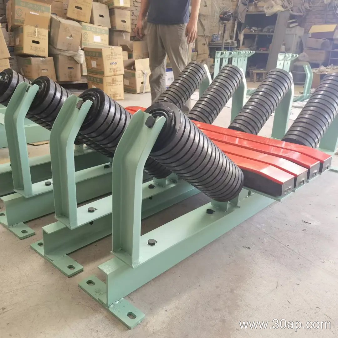
A typical idler has a steel tube shell, a shaft, bearing housings, and seals. The shell surface may be plain steel, nylon, rubber rings, or ceramic, depending on the duty. Rubber rings, for example, are common on buffer idlers where impact from large lumps is heavy. Ceramic or nylon can be chosen when sticking or abrasion is a concern.
Bearings are usually deep groove ball bearings. Common sizes include 6204, 6205, 6305, 6306, 6308, and 6310. These are not tied to one roller diameter; a given roller diameter may use different bearing sizes depending on load and design. The seal is critical. Labyrinth seals and contact seals are used to keep fine aggregate dust out of the bearing cavity. Once dust enters, the roller stiffens, the belt drags, and power consumption rises.
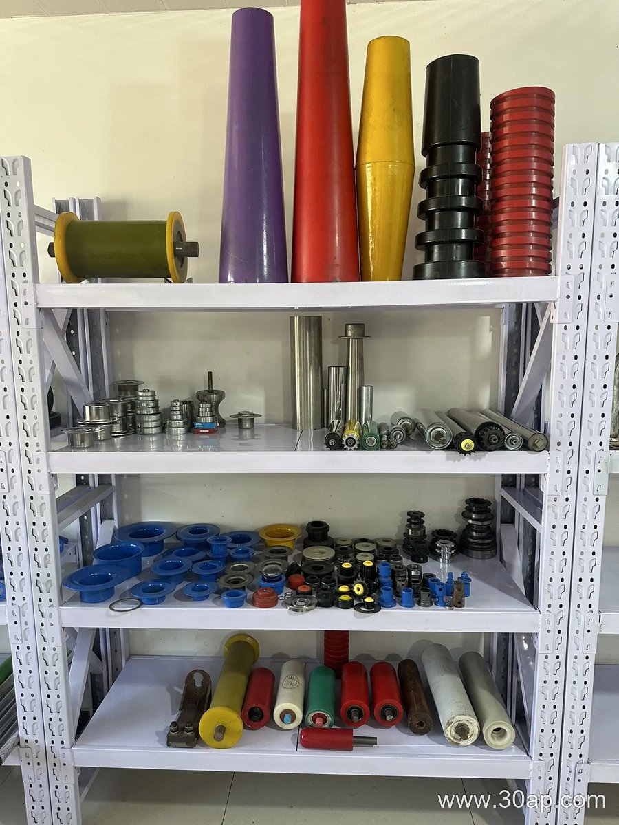
Roller diameter is another variable. Common diameters include 63 mm, 76 mm, 89 mm, 102 mm, 108 mm, 127 mm, 133 mm, 159 mm, 178 mm, 194 mm, and 219 mm. A larger diameter generally suits higher belt speeds or heavier loads. Roller length changes with belt width, trough angle, and the idler set arrangement. For a three-roll troughing set, common roll lengths are about 200 mm for B500, 250 mm for B650, 315 mm for B800, 380 mm for B1000, 465 mm for B1200, 530 mm for B1400, 600 mm for B1600, 670 mm for B1800, and 750 mm for B2000. These are examples, not fixed rules. Side rolls and center rolls can differ, and the engineer will confirm the final dimensions.
Where It Is Used in an Aggregate Line
Aggregate production covers several stages: primary crushing, secondary crushing, screening, and stockpiling. Idlers appear on every belt between these stages. A common arrangement on the carrying side is a three-roll troughing idler set with a 20, 30, 35, or 45 degree trough angle. The trough angle shapes the belt into a curve so material stays centered. On the return side, flat return idlers or V-shaped return idlers support the empty belt.
At a loading point below a crusher or screen, buffer idlers with rubber rings absorb impact. Along a long straight run, training idlers help correct belt misalignment. In a limestone quarry or a sand and gravel plant, dust and moisture are constant, so sealing quality often decides how long an idler lasts.
Other components in the same system include the conveyor pulley at the drive and tail positions, and the conveyor bracket that fixes each idler to the frame. These are separate parts with separate functions. A drive pulley transmits power; a tail pulley redirects the belt; a bend pulley changes direction. None of them should be used as a substitute name for an idler.
What a Buyer Should Check
Before ordering, confirm the belt width, the trough angle, and the idler set type. A single-roll, two-roll, or three-roll arrangement will change the roll length and the load per bearing. Check the roller diameter and shaft size as a matched pair, not as independent numbers. A wider belt does not automatically mean a specific shaft diameter; the design load and the frame bracket determine that.
Ask about the seal type and the bearing brand only if the supplier can document them. Avoid assuming that a larger roller diameter is always better. In a fine aggregate circuit, a smaller diameter may fit a tighter frame and still carry the load. In a primary crushing discharge with heavy lumps, a larger diameter and a rubber-ring surface usually make more sense.
Also consider maintenance. Idlers that can be replaced one by one, without removing the whole bracket, save downtime. Keep a few spare rollers on site, especially for the loading zone. A worn idler can damage the conveyor belt edge and increase spillage, so early replacement is cheaper than a belt repair.
Selection Summary
An aggregate production line idler is a simple rotating part with a large effect on belt life and plant uptime. Choose the roller diameter, length, bearing, seal, and surface form to match the belt width, trough angle, material, and environment. Use common sizes as a starting point, then confirm with the conveyor designer. Keep drive, tail, and bend pulleys in their own category, and treat the idler as the supporting element it is.
What a Conveyor System Pulley Does
A conveyor system pulley is the rotating drum that guides, drives, or tensions the conveyor belt in a bulk material handling line. It is not simply a roller with a shaft. The pulley transfers motion and force between the drive unit and the belt, or it changes the belt path and maintains the required tension so material moves reliably from one point to another.
In everyday plant language, people often call this component a conveyor drum or belt pulley. These are accurate equivalent names for the same product. A drive pulley, a tail pulley, and a bend pulley, however, are not interchangeable. Each has a different position and duty in the conveyor layout, and selecting one as if it were another can lead to belt slip, tracking problems, or premature component wear.
How a Conveyor Pulley Is Built
The basic structure includes a cylindrical shell, end discs, a shaft, and often a hub and locking assembly. The shell is usually made from steel plate or seamless pipe and is machined or balanced for smooth rotation. The shaft size is determined by torque and load, not by belt width alone. Common shaft diameters include Ø50, Ø60, Ø80, Ø100, Ø120, Ø160, and Ø200, but the final value depends on the drive power, belt tension, and bearing arrangement.
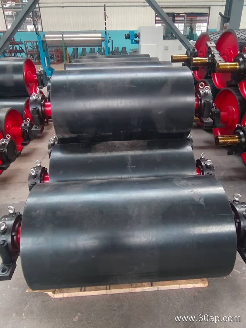
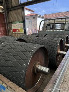
The surface form is another important part of the build. A plain steel shell may be used where grip is not critical. Rubber lagging can be applied by hot vulcanization, cold bonding, or as a cast rubber layer. Diamond grooved lagging and herringbone lagging are common choices for improving traction and shedding water or fine material. Ceramic lagging may be considered where abrasive conditions and high slip risk exist. Typical lagging thicknesses include 8 mm, 10 mm, 12 mm, 15 mm, and 20 mm, but these values should be confirmed against the actual duty.
Drive, Tail, and Bend Pulley Positions
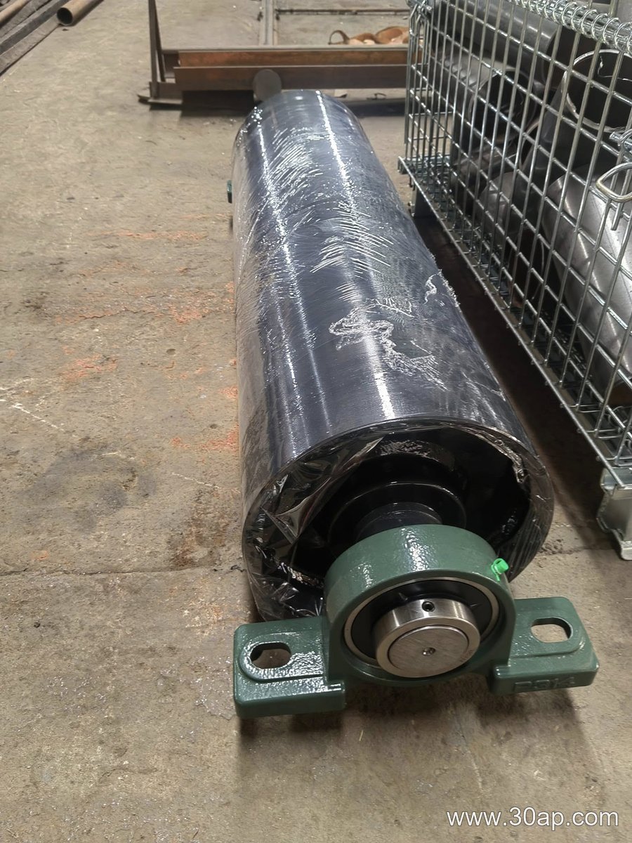
A drive pulley, also called the head pulley when it sits at the discharge end, receives power from the gearbox and transmits it to the conveyor belt. It usually has lagging to increase friction. A tail pulley sits at the loading end and often serves as a tensioning point. A bend pulley changes the belt direction without driving or tensioning it, and it may be plain or lagged depending on the application. A take-up pulley works with the tensioning system, while a snub pulley increases the wrap angle around the drive pulley.
These positions are not the same. A bend pulley cannot replace a drive pulley, and a tail pulley should not be specified as a bend pulley simply because the dimensions look similar. The duty, load, and belt wrap requirements differ.
Where Conveyor System Pulleys Are Used
Bulk material handling relies on these pulleys in many locations. In a quarry or sand and gravel plant, they move crushed stone and aggregate along the main conveyor. In a coal handling system at a power plant, they support continuous fuel flow from stockpile to boiler. In a concrete batching plant, they feed sand, gravel, and cement to the mixer. In a grain silo or fertilizer plant, they handle relatively light but continuous loads.
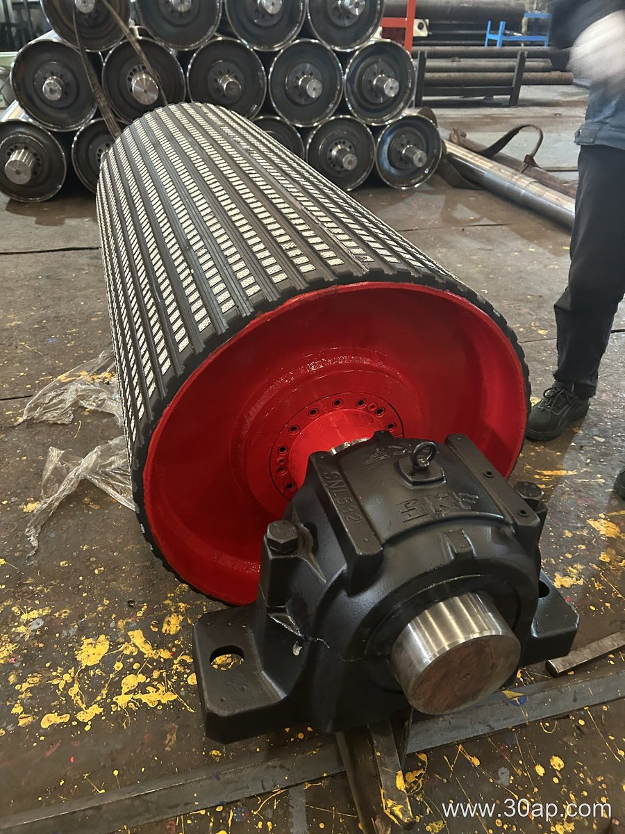
The working environment affects the specification. Dust, moisture, temperature, and abrasive fines all influence the choice of lagging, bearing seals, and shaft material. For example, a conveyor system pulley in a wet aggregate line may need grooved rubber lagging to reduce slip, while a clean grain conveyor may run with a plain or lightly lagged surface.
Matching Pulley Diameter and Belt Width
Belt width and pulley diameter are related, but they are not locked in a fixed one-to-one match. A wider belt generally requires a wider pulley face, and the pulley face is usually somewhat wider than the belt itself. Common face widths include about 500 mm for B400, 600 mm for B500, 750 mm for B650, 950 mm for B800, 1150 mm for B1000, 1400 mm for B1200, 1600 mm for B1400, 1800 mm for B1600, 2000 mm for B1800, 2200 mm for B2000, and 2400 mm for B2200. These are reference values, not universal rules.
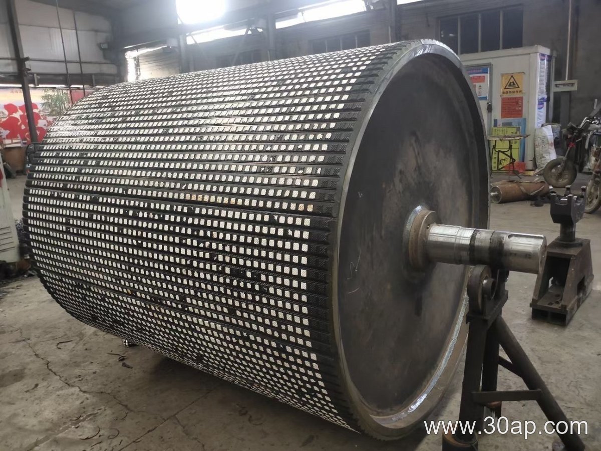
Diameter selection depends on belt tension, the number of plies or steel cord construction, the required wrap angle, and the drive torque. A B800 conveyor might use a Ø500 pulley in one layout and a larger diameter in another if the belt construction or tension demands it. A B1200 system may use a Ø1000 drive pulley, while a B1400 line may use a Ø800 bend pulley. The combination should come from the conveyor design, not from a simple table.
What Buyers Should Check
- Confirm the pulley function: drive, tail, bend, take-up, or snub. Do not order by position name alone.
- Check the belt width and required face width, but do not assume one belt width has only one possible diameter.
- Review the shaft diameter against torque and load. Do not derive a fixed shaft size from belt width alone.
- Choose the surface form for the actual conditions: plain, rubber lagged, diamond, herringbone, or ceramic.
- Match the pulley to the conveyor bracket arrangement and bearing type so the assembly fits the frame.
- Ask for the balancing standard, runout tolerance, and lagging thickness if the application is demanding.
A conveyor belt, idler roller, and conveyor bracket all interact with the pulley, so the whole system should be reviewed together. A pulley that is correct in isolation can still perform poorly if the belt tracking, loading, or take-up system is not set up properly.
Maintenance and Wear Points
Routine inspection should cover lagging wear, shell cracks, shaft deflection, bearing temperature, and belt tracking. Lagging that becomes smooth or glazed can reduce drive traction, especially in wet conditions. Worn end discs or loose locking assemblies can cause vibration and premature bearing failure. When replacing a pulley, record the original dimensions, position, and surface type so the new unit matches the duty rather than just the footprint.
For a reliable conveyor system pulley, the key is to treat it as an engineered component. The right shell, shaft, lagging, and bearing choice comes from the conveyor duty, not from a single number on a drawing. Buyers who share the belt width, material, tonnage, drive power, and position with the supplier will get a more accurate recommendation and fewer surprises during installation.
What a Three-Roll Idler Bracket Does
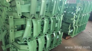
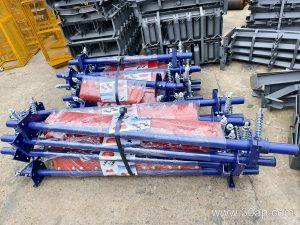
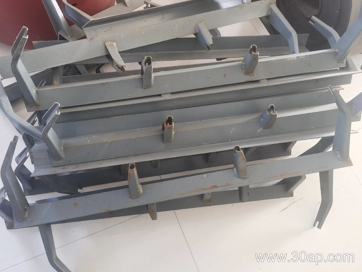
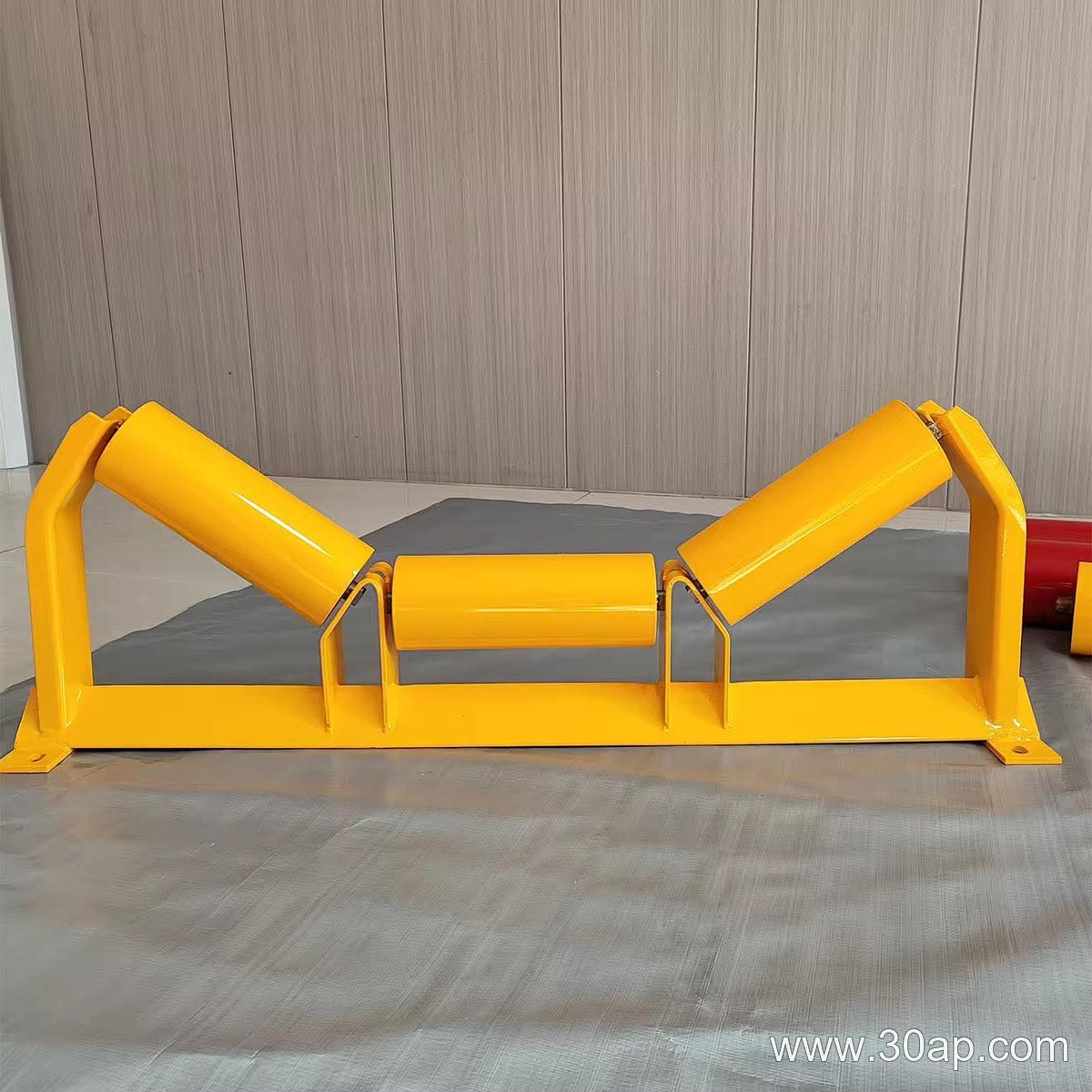
A three-roll idler bracket is the support structure that holds three idler rollers in a trough shape under the carrying side of a conveyor belt. In everyday plant language it is also called a troughing idler bracket or a three-roller idler frame. The bracket keeps the center roller horizontal and tilts the two outer rollers upward, so the belt forms a trough that contains bulk material during transport. It is a structural part, not a rotating part, but its geometry directly affects how the belt tracks, how the load sits, and how long the rollers last.
The bracket should not be confused with a conveyor pulley. Drive, tail and bend pulleys are different components with different jobs; they transmit power or change belt direction. A three-roll idler bracket simply carries the belt between those pulleys. The same distinction applies to a return bracket, which supports the empty belt on the way back, and to a V-return bracket, which is used only for that return run. Those are separate subtypes, not interchangeable names for the troughing bracket.
How the Bracket Is Built
Most three-roll idler brackets are fabricated from angle steel, channel steel, or bent steel plate. The frame usually consists of a base beam and two inclined arms or slots that position the side rollers at the required trough angle. Roller shafts sit in machined or punched seats, and the whole assembly bolts to the conveyor stringer or frame. Some designs use a fixed geometry, while adjustable brackets allow the trough angle to be changed within a range.
Common trough angles include 20 degrees, 30 degrees, 35 degrees, and 45 degrees. A 20-degree bracket is often chosen for light, free-flowing material or where belt training is difficult, while 35 degrees and 45 degrees are used where a deeper trough is needed to increase capacity. Adjustable brackets can be set between these angles, but the setting should follow the belt width, material characteristics, and the conveyor designer’s recommendation rather than a fixed rule.
Where It Fits on the Conveyor
The bracket is mounted on the carrying side of the conveyor, usually at intervals along the idler station. It works together with the conveyor belt, the idler rollers, and the main conveyor frame. The center roller supports the middle of the belt, and the two side rollers support the edges. When the belt is loaded, the trough shape keeps material from spilling over the edges and helps the belt run centered.
Typical applications include crushing and screening plants, sand and gravel lines, coal handling in power stations, and fertilizer or grain silo discharge systems. In a quarry or limestone mine, a three-roll bracket is often used on the main haulage conveyor where the belt carries coarse rock. In a cement plant or steel plant, the same bracket type may appear on clinker or sinter conveyors, but the selected trough angle and roller diameter will differ according to the duty.
Matching Bracket, Belt Width, and Roller Diameter
Belt width and roller diameter are related but not locked together. A bracket for B800 belt may accept rollers with a shaft seat sized for Ø89 or Ø108 rollers, depending on the frame design. A B1200 conveyor might use Ø133 or Ø159 rollers with a 35-degree or 45-degree trough. A B650 belt with a 30-degree trough and Ø89 rollers is also a common combination. These are examples, not fixed pairings. The mounting hole spacing and beam length change with belt width and trough angle, so the bracket must be ordered for the specific conveyor configuration.
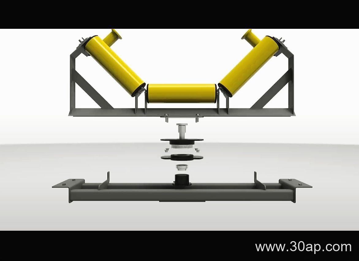
Buyers should confirm the belt width, trough angle, roller diameter, roller shaft type, and mounting hole pattern before ordering. If the bracket is adjustable, check the adjustment range and the locking method. If it is a fixed bracket, confirm that the angle matches the existing idler set. A bracket that fits one conveyor may not fit another, even if both conveyors use the same belt width.
Fixed, Adjustable, and Transition Brackets
A fixed three-roll idler bracket holds the rollers at one trough angle. It is simple, rigid, and usually lower in cost. An adjustable bracket has slots or pivoting arms that let maintenance staff change the trough angle or fine-tune belt contact. Adjustable designs are useful when material conditions change or when a conveyor is being recommissioned for a different duty.
Transition brackets are a related subtype used near pulleys, where the belt changes from flat to trough. They are not the same as a standard three-roll bracket, but they may share similar construction. Impact brackets, which are used under loading points, are another subtype. Each has its own place, and none should be substituted for the main troughing bracket without checking the belt line and load conditions.
What to Check Before Buying
- Confirm the belt width and the required trough angle.
- Match the roller diameter and shaft end to the bracket seat.
- Check the mounting hole spacing and beam length against the conveyor frame.
- Decide whether a fixed or adjustable bracket suits the application.
- Verify the material and finish for the site environment, such as dust or moisture.
- Ask for the bracket drawing or dimensional data before placing an order.
A three-roll idler bracket is a small part of a conveyor system, but it affects belt training, material containment, and roller life. Choosing the right trough angle and mounting dimensions for the actual conveyor is more important than choosing a bracket by name alone. When the bracket, idler roller, and conveyor belt work together correctly, the carrying run stays stable and the maintenance interval becomes more predictable.