What a Carbon Steel Conveyor Bracket Does on the Line
A carbon steel conveyor bracket is the structural interface between the conveyor frame and the rollers that carry or return the belt. In practice, it is the fabricated steel part that holds an idler roller at the correct height, angle, and spacing so the conveyor belt runs true under load. Buyers in a limestone quarry, a cement plant, or a power station coal yard often treat this component as a small item, yet it decides how evenly the belt is supported and how quickly a roller can be replaced during a shift.
The same item is also described as a carbon steel idler bracket or a steel conveyor roller support. These are equivalent names for the same product; the material, not the name, is the defining point. Carbon steel offers good weldability, predictable stiffness, and a cost level that suits long conveyor lines with many support stations.
How the Bracket Is Built
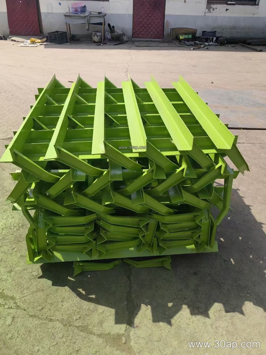
Most units are made from angle steel, channel steel, or folded steel plate. The fabrication route is straightforward: cutting, punching or drilling mounting holes, bending to the required trough angle, welding the gussets and roller seats, then surface treatment such as painting or galvanizing. A well-made bracket keeps its geometry after welding, because distortion at the roller seat will show up as belt misalignment later.
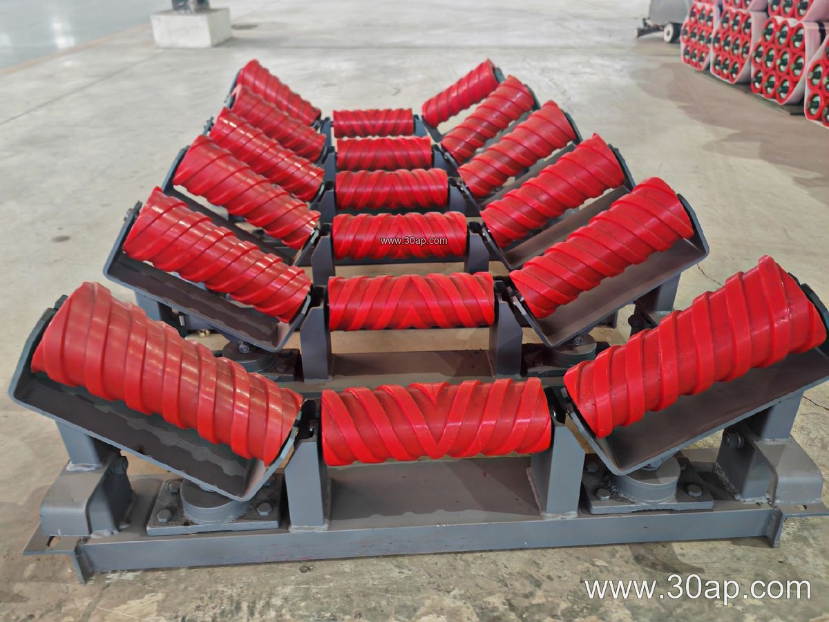
Key build details a buyer can check:
- Roller seat spacing and hole pitch matched to the actual idler roller shaft ends.
- Beam length and mounting hole positions matched to the conveyor frame width.
- Weld quality at the angle joints, where vibration fatigue usually starts.
- Coating thickness and coverage on edges and drilled holes.
Because hole pitch and crossbeam length change with belt width and trough angle, these values should be confirmed against the drawing rather than assumed from a catalogue number.
Common Forms and Where They Sit
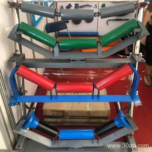
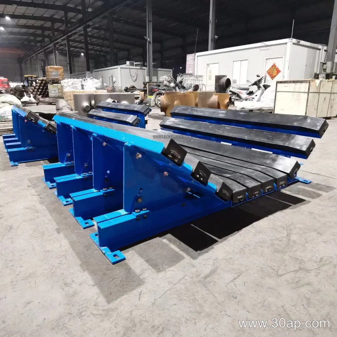
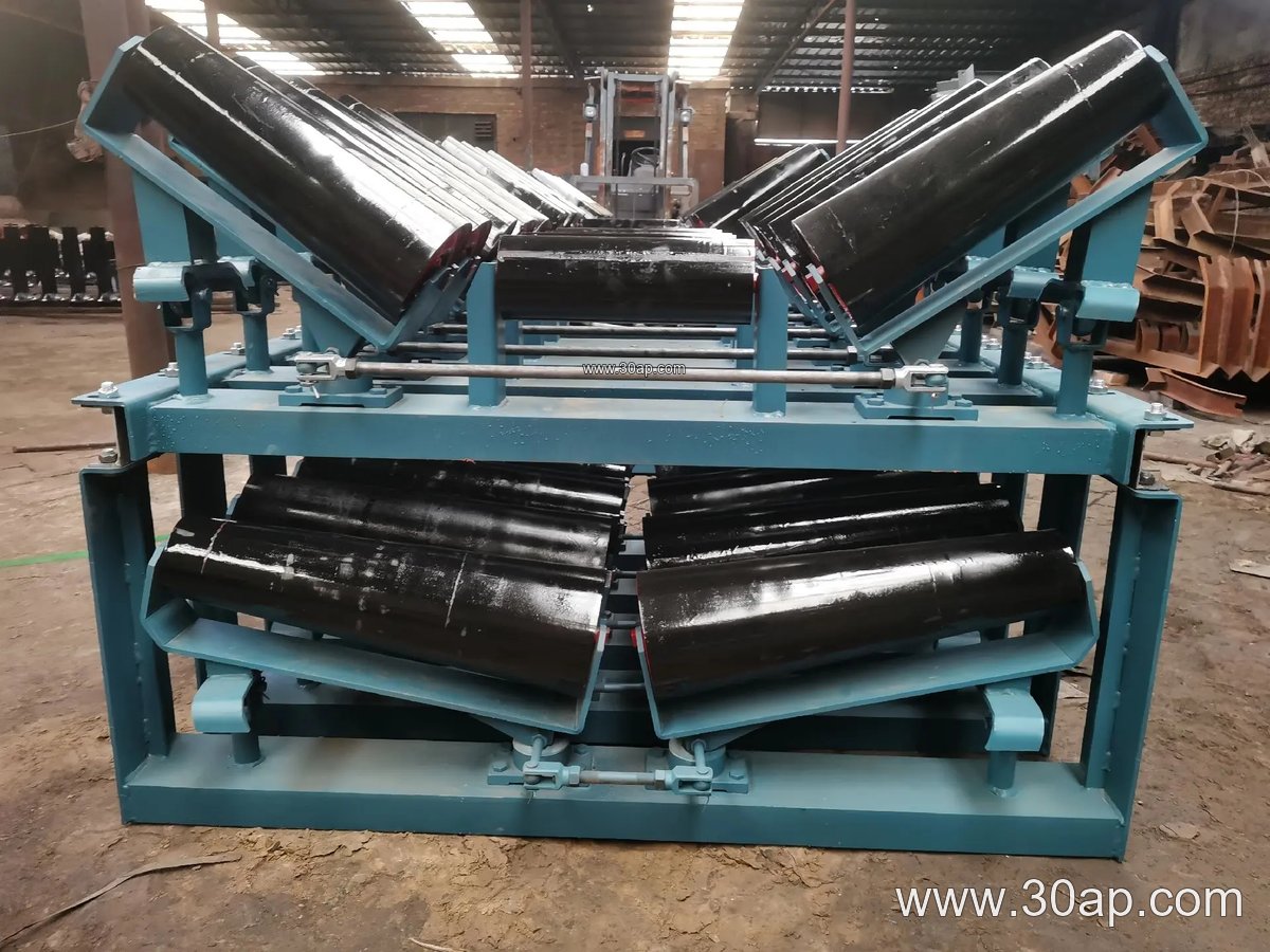
Support brackets are not one shape. The troughing bracket carries three rollers in a trough profile on the carrying side. A transition bracket sits near the pulleys, where the belt changes from troughed to flat. On the return side, a flat return bracket or a V-shaped return bracket holds the belt up after discharge. Impact brackets with cushioning are placed under the loading point, and self-aligning brackets are used where the belt tends to wander.
Adjustable brackets allow the trough angle to be set on site, which is useful when the same frame design serves several belt widths. Fixed brackets are simpler and stiffer, and they suit lines where the profile never changes. A slight forward tilt of about 1.5 to 2 degrees is sometimes built into the carrying bracket to help centre the belt.
Typical Reference Combinations
The table below shows common reference pairings only. They are design examples, not fixed rules, and one belt width can be paired with more than one trough angle or roller diameter.
| Belt width | Trough angle | Roller diameter | Typical bracket use |
|---|---|---|---|
| B650 | 30 degrees | Ø89 | Light aggregate or sand line |
| B800 | 35 degrees | Ø108 | General bulk handling |
| B1000 | 35 degrees | Ø133 | Crushing and screening plant |
| B1200 | 45 degrees | Ø133 | Heavy troughing, high capacity |
| B1400 | 35 degrees | Ø159 | Cement plant clinker line |
| B1600 | 45 degrees | Ø159 | Ore transport, long spans |
| B1800 | 35 degrees | Ø194 | Port and bulk terminal |
Trough angles of 20, 30, 35, and 45 degrees cover most needs, with adjustable versions able to move between them. Roller diameters of Ø89, Ø108, Ø133, Ø159, and Ø194 are the usual range. When a wide belt such as 1800mm is used, the bracket must be stiff enough to resist deflection between supports.
Matching the Bracket to Belt and Roller
The bracket, the conveyor belt, and the conveyor pulley all influence each other. A heavy-duty mining conveyor belt carrying iron ore needs closer support spacing than a light aggregate belt, and that spacing is set by the bracket layout. At the discharge end, the belt path is governed by the head pulley, so the transition bracket must follow the pulley geometry rather than an arbitrary angle.
Material choice on the belt side matters too. A heat resistant conveyor belt used in a cement kiln area, or a flame retardant conveyor belt in a coal yard, does not change the bracket design directly, but the surrounding dust and temperature do affect coating selection. In a fertiliser or grain silo, corrosion protection becomes more important than pure load capacity.
Buyer Checklist Before Ordering
- Confirm belt width and trough angle, and state whether the bracket is fixed or adjustable.
- Give the roller diameter and the exact shaft end shape, so the seat fits.
- Provide frame drawings showing mounting hole centres and beam length.
- State the environment: washdown, dust, coastal air, or high temperature.
- Ask for the coating specification and check welds on a sample.
Spare parts planning deserves attention as well. Keeping a small stock of the most common bracket type on site shortens downtime when a roller seizes. Further reference drawings for related parts can be found at gslconveyor.com, covering belt and roller support arrangements.
Installation and Maintenance Notes
Alignment is the main installation task. Brackets should be set square to the frame centreline, with consistent height across the line. A single bracket sitting a few millimetres high will lift the belt locally and start edge wear. During maintenance, check for loose bolts, cracked welds, and paint failure at the base, since moisture collects there. Replacing a worn bracket early is cheaper than replacing the belt edge it damages.
For lines handling abrasive rock or sinter, inspect the loading zone brackets more often. For a quarry conveyor belt or a crusher conveyor belt, the impact area is where brackets take the hardest knocks.