Why Belt Tracking Needs More Than a Standard Bracket
On a long overland conveyor at a quarry, or a transfer line inside a cement plant, a belt that drifts sideways is a maintenance problem that rarely fixes itself. The self-aligning idler bracket is the component that turns ordinary carrying idlers into a corrective system. Instead of holding the roller in a fixed position, this bracket allows the idler frame to pivot slightly when the belt wanders, so the roller steers the belt back toward the center line.
The assembly is sometimes called a self-tracking idler bracket or a swivel idler bracket. It is not a substitute for a drive pulley, tail pulley, or bend pulley; those components transmit power and change belt direction, while the bracket works only on the carrying or return side to control lateral position.
How the Bracket Is Built
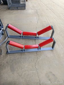
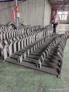
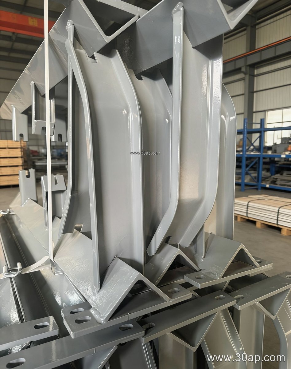
Most units combine a fixed base, a pivoting frame, and a vertical pivot axis. The base is typically fabricated from angle steel, channel steel, or folded steel plate, with mounting holes that match the conveyor stringer spacing. The moving frame carries the idler roller, and a small amount of rotation is enough to create a steering effect. Some designs add a forward tilt of about 1.5 to 2 degrees to help the roller lead the belt gently back into line.
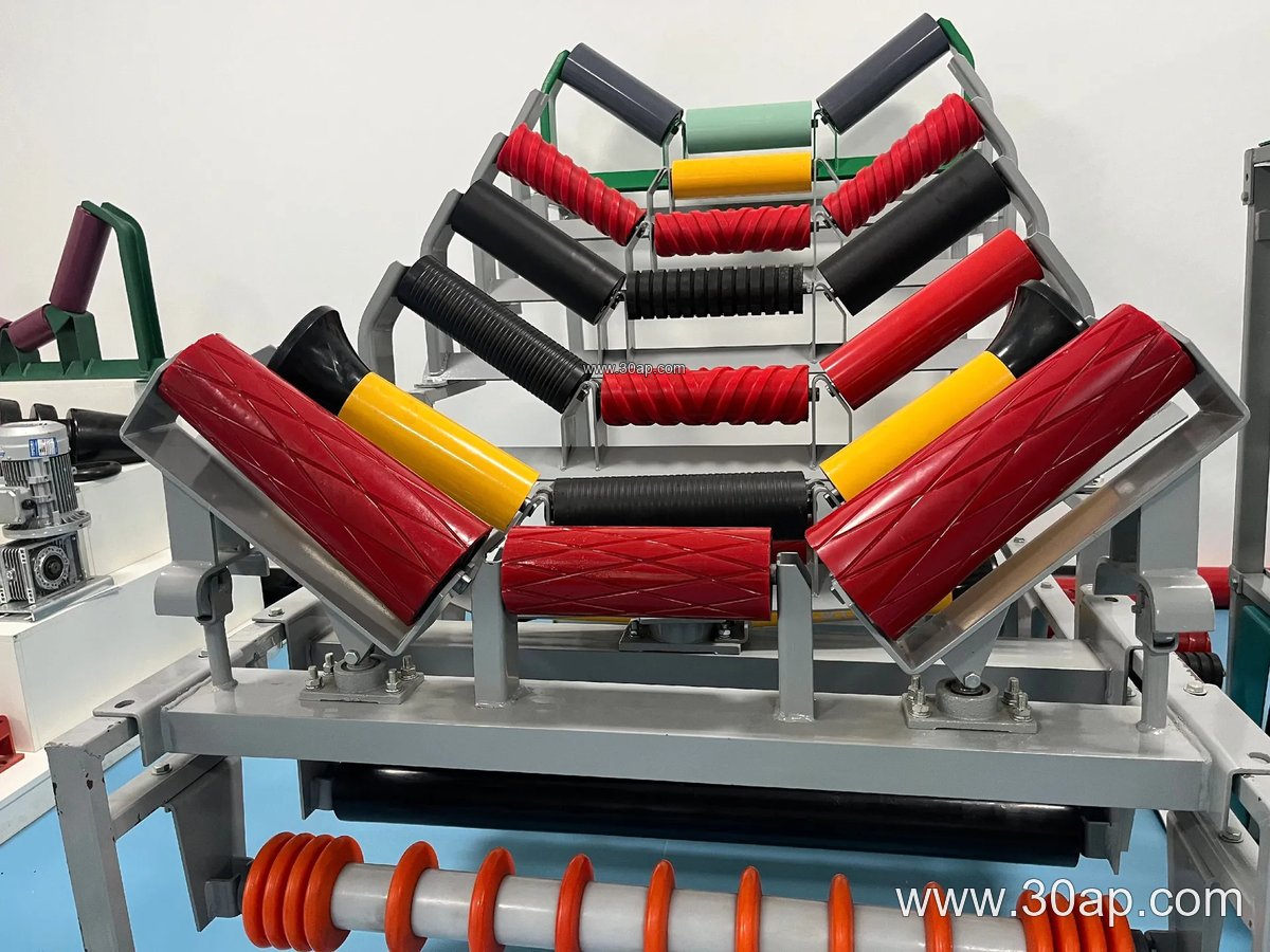
- Pivot pin or bearing seat at the center of rotation
- Stop lugs that limit travel and prevent over-correction
- Adjustment slots for fine setting during installation
- Galvanized or painted finish for dusty, humid environments
Because the frame moves, the bracket must be rigid enough to carry the belt load without flexing, yet free enough to respond to small tracking errors. Worn pivot bushings or seized pins are common causes of poor performance, so greasable or sealed pivot points are worth checking at the design stage.
Where It Fits on the Conveyor
Self-aligning brackets are usually installed at intervals along the carrying run, often after loading points where material impact can push the belt off center. In a coal handling system or a power plant coal yard, they may be placed on the return side as well, paired with V-return idlers. A typical arrangement on a B1000 conveyor might use a 35-degree trough angle with Ø108 idlers, while a B1200 line in a limestone crushing circuit could run 45-degree troughing with Ø133 rollers. These are common references, not fixed rules; the final combination depends on belt width, load, and the conveyor designer’s tracking plan.
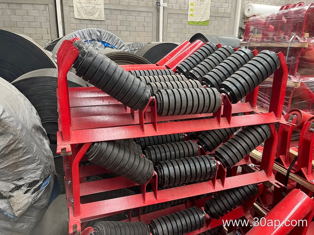
Onsite, the bracket is often confused with a training idler assembly. The two work together: the idler roller contacts the belt, and the self-aligning bracket provides the pivoting motion. A standard fixed bracket, by contrast, keeps the roller square to the frame and offers no correction. On a steel cord conveyor belt or a heavy-duty mining conveyor belt, the extra stiffness of the belt means the bracket’s response must be smooth rather than abrupt.
Applications Across Bulk Handling
Tracking problems appear wherever belts carry abrasive or uneven loads. In a sand and gravel line, a fabric core conveyor belt may drift after a crusher discharge; in an iron ore terminal, a steel cord conveyor belt moving at high tension needs stable, predictable correction. Self-aligning brackets are also found in cement plants, lime kiln feed lines, fertilizer granulation plants, and tunnel muck removal conveyors.
When the belt itself is the source of mistracking, check belt splices, edge damage, and material build-up on rollers before blaming the bracket. A chevron conveyor belt or corrugated sidewall conveyor belt can behave differently from a flat belt, and a pipe conveyor belt has its own centering requirements that a standard self-aligning bracket cannot address.
What Buyers Should Confirm
Before ordering, match the bracket to the conveyor’s belt width and idler diameter, and confirm the mounting hole spacing on the stringers. Key details include:
- Belt width range, for example B650, B800, B1000, or B1200
- Trough angle, commonly 20, 30, 35, or 45 degrees, with adjustable versions covering a range
- Idler diameter, such as Ø89, Ø108, Ø133, or Ø159
- Material and finish for the site conditions
- Pivot type and lubrication requirements
Ask for a dimensional drawing showing the pivot center, frame length, and hole pattern. Installation height and crossbeam length vary with belt width and trough angle, so they should be confirmed per project rather than assumed. During commissioning, align the bracket square to the belt line, allow a small amount of free travel, and observe tracking over several running hours before final tightening.
For operators sourcing conveyor components, it also helps to review the belt specification alongside the bracket choice. A heat resistant conveyor belt in a clinker line, an oil resistant conveyor belt in a recycling plant, or a flame retardant conveyor belt in an underground coal mine all place different demands on the idler and bracket assembly. Matching the self-aligning idler bracket to the actual belt, load, and environment is the most reliable way to keep a conveyor centered.