What a Conveyor Support Leg Does on a Belt Conveyor
A conveyor support leg is the vertical structural member that carries the weight of the conveyor frame, idler sets, and the loaded belt down to the floor, foundation, or steel structure. In a typical trestle or gallery arrangement, these legs are paired with longitudinal beams and cross members to form the supporting frame. The leg itself is a simple component, but it sets the elevation of the belt line, controls the spacing between idler stations, and influences how easily the whole conveyor can be leveled and aligned during installation.
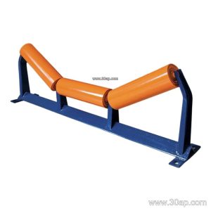
On quarry and aggregate lines, the support leg often works together with a heavy-duty conveyor belt and a series of idler rollers to keep material moving smoothly from the crusher to the screening plant. On coal handling and power plant coal yards, the same structural role applies, though the frame may need to accommodate fire retardant belting and additional walkways.
Construction and Materials
Most conveyor support legs are fabricated from structural steel rather than cast or molded parts. Common materials include:
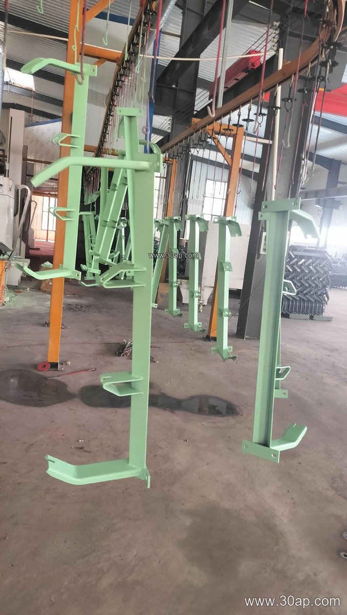
- Angle steel for lighter frames and shorter spans
- Channel steel for medium-duty trestles and long conveyor lines
- Folded steel plate for heavier loads or where a closed profile is preferred
The leg is usually welded or bolted to a base plate, which is then anchored to a concrete foundation or bolted to a structural steel beam. Adjustable versions include slotted holes or threaded height-adjustment sections so the installer can fine-tune the belt line before final tightening. Fixed legs are simpler and cheaper but require more accurate foundation work.
Mounting hole spacing and crossbeam length are not universal. They change with belt width, trough angle, and the idler frame type used, so a leg drawing should always be matched to the specific conveyor layout rather than selected from a single table.
Where Support Legs Are Used
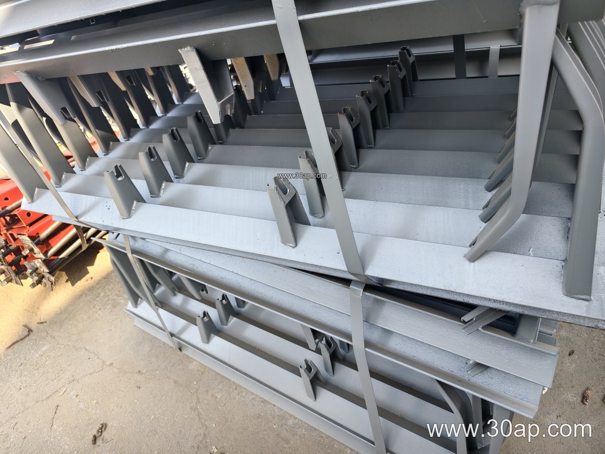
Support legs appear wherever a belt conveyor must be elevated above ground or above a working floor. Two common settings illustrate the range:
- Sand and gravel plants: legs carry the transfer conveyors between crushers and screens, often on a steel trestle with a 35-degree trough and Ø108 idlers on a B800 belt.
- Cement plant clinker lines: heavier frames support abrasion resistant belting and larger idler diameters, with legs spaced according to the loaded belt weight and the allowable deflection of the longitudinal beams.
Similar arrangements are found in iron ore handling, tunnel muck removal, and grain silo discharge systems, where the conveyor frame must stay level and stable over long distances.
Matching the Leg to Belt Width, Trough Angle, and Roller Diameter
The support leg is part of a frame system, so its dimensions follow the belt and idler selection rather than the other way round. A few reference combinations are common in design drawings:
| Belt Width | Trough Angle | Typical Idler Diameter | Frame Note |
|---|---|---|---|
| B500 | 20° or 30° | Ø89 | Light trestle, angle steel legs |
| B650 | 30° | Ø89 or Ø108 | Standard quarry transfer frame |
| B800 | 35° | Ø108 | Common aggregate and cement line |
| B1000 | 35° or 45° | Ø133 | Channel steel legs, longer spans |
| B1200 | 45° | Ø133 or Ø159 | Heavy-duty trestle, bolted base plates |
| B1400–B1600 | 35° or 45° | Ø159 or Ø194 | Mining and port conveyor frames |
These are reference examples, not fixed rules. A B1000 belt can be paired with different trough angles or roller diameters depending on load, speed, and material characteristics. The leg drawing should state the actual crossbeam length, hole pitch, and height required by the project.
Fixed vs Adjustable Legs
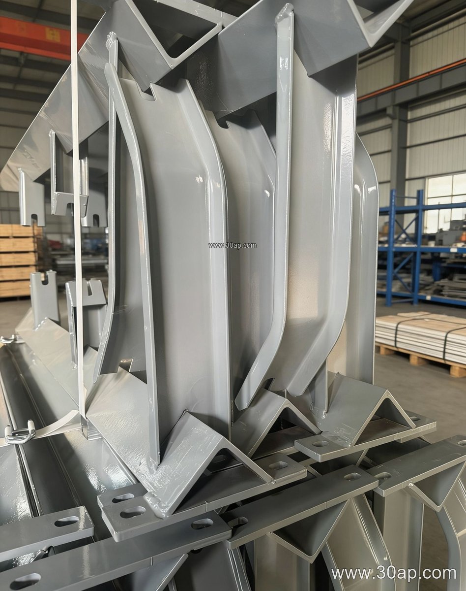
Fixed support legs are welded to the frame or bolted with a single position. They suit conveyors where the foundation is precise and the belt line does not need later correction. Adjustable legs allow vertical movement and sometimes lateral correction, which helps during installation and when ground settlement occurs. For long overland or stockyard conveyors, a mix of fixed and adjustable legs is often used, with adjustable units placed at transition points or near the drive and tail pulleys.
When the frame includes a conveyor pulley, the support leg near the pulley should be checked for additional loads from belt tension. A conveyor bracket at the pulley bearing housing is a separate component from the leg, but both must align with the same structural grid.
Buyer Checklist
- Confirm belt width, trough angle, and idler diameter before ordering legs.
- Ask for the crossbeam length, mounting hole pitch, and overall height as project-specific values.
- State the material and finish, such as painted or galvanized steel.
- Check whether the leg is fixed or adjustable and how much adjustment is needed.
- Match the base plate to the foundation or steel beam detail.
- Consider the belt type in service, from a flame retardant conveyor belt in a coal yard to a heat resistant belt near a clinker cooler, because belt weight and tension affect frame loads.
A well-matched support leg keeps the idler frames level, protects the belt from misalignment, and gives maintenance crews a stable structure to work from.