What the Support Frame Does
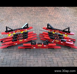
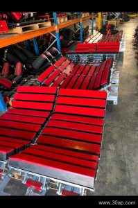
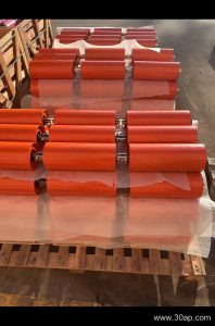
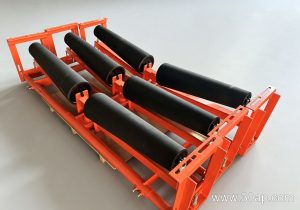
A conveyor belt support frame is the steel structure that holds the idler rollers in the right position under and over the belt. It carries the weight of the belt, the material on it, and the rollers themselves, and it keeps the trough shape consistent along the run. In a quarry, a coal washing plant, or a cement clinker line, the frame is the part that quietly decides whether the belt tracks straight or wanders.
The frame is not a single item. It is a family of brackets and beams, and the correct term for the general product is a conveyor belt support frame, while individual pieces are often called conveyor brackets when they are bolted to the main stringer.
How It Is Built
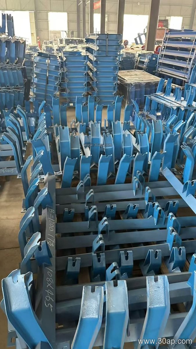
Most frames are fabricated from angle steel, channel steel, or folded steel plate. The crossbeam spans the conveyor stringers, and the bracket ends are punched or slotted so the roller shaft can sit at the designed trough angle. Welded frames are common for fixed installations; bolted frames are easier to ship and to replace on site.
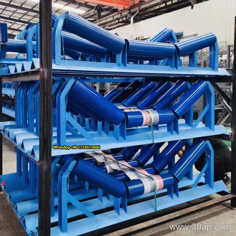
Key structural points a buyer should confirm:
- Crossbeam length and hole spacing, which change with belt width and trough angle rather than following one fixed number.
- Bracket height, which must match the selected roller diameter.
- Surface treatment, since dust and moisture in a coal plant or a fertilizer storehouse punish unprotected steel.
Common Configurations
The table below shows typical reference values used when specifying frames. These are examples, not compulsory combinations, and the final figures are set by the conveyor design.
| Frame type | Typical belt width | Trough angle | Roller diameter | Where it fits |
|---|---|---|---|---|
| Carrying trough frame | B800, B1000 | 30 degrees, 35 degrees | Ø89, Ø108 | Main haul in a sand and gravel line |
| Transition frame | B1200, B1400 | 20 degrees to 35 degrees | Ø133, Ø159 | Near the head pulley, easing the belt into the trough |
| Return flat frame | B650, B800 | Flat | Ø89, Ø108 | Return strand in a limestone mine |
| V-return frame | B1000, B1200 | V form | Ø108, Ø133 | Self-cleaning return in a power plant coal yard |
| Impact frame | B1200, B1600 | 30 degrees, 35 degrees | Ø133, Ø159 | Below the loading chute at a crushing station |
| Self-aligning frame | B800 to B1400 | 30 degrees, 35 degrees | Ø108, Ø133 | Long runs where belt wander is a risk |
Adjustable frames allow the trough angle to be set between positions, for example from 20 degrees up to 45 degrees, and they suit lines where the belt is changed or where the material load varies. Forward-tilted frames, usually around 1.5 to 2 degrees, are used to help center the belt. Fixed frames are simpler and cheaper, and they are the usual choice once the layout is settled.
Where It Is Used
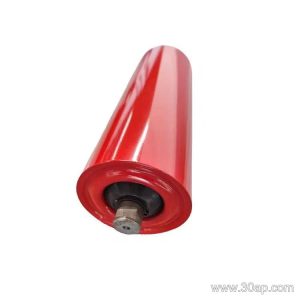
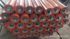
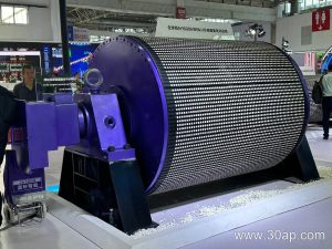
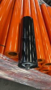
You will find these frames in almost any bulk handling line, but the demands differ. In a tunnel muck line the frame must tolerate shock loading and grit. In a grain silo the priority is a clean, smooth trough so product does not lodge. In a steel sintering plant the frame sits close to heat and needs the right roller spacing, since a support frame and its idler roller work as one unit and cannot be judged separately. A conveyor pulley at the drive or tail end sets the belt path, but it does not replace the frame’s job along the run.
Selection Points for Buyers
Start from the belt width and the required trough angle, then pick the roller diameter that suits the load and the belt speed. Check that the bracket hole spacing matches the roller shaft you intend to fit. Confirm the material thickness and the coating for your site conditions. If the line may be modified later, an adjustable frame is worth the extra cost. Ask for the crossbeam drawing, because two frames with the same belt width can differ in hole layout.
Finally, plan for maintenance. Frames that allow a single roller to be lifted out without dismantling the whole crossbeam save hours in a working plant.