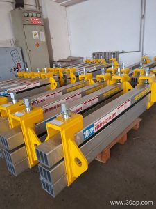
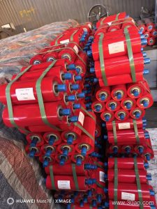
What the Head Pulley Does on a Belt Conveyor
The belt conveyor head pulley, often called the drive pulley or discharge pulley, sits at the delivery end of the conveyor. It has two jobs at once. First, it transmits torque from the gearbox to the conveyor belt, pulling the loaded belt forward. Second, its cylindrical surface supports the belt as it changes direction and sheds material into the transfer chute or stockpile. Because it handles both power transmission and belt guidance, its diameter, face width, shaft, lagging, and bearing arrangement all matter. In a quarry, cement plant, or coal handling system, this one component strongly influences belt tracking, belt life, and overall uptime.
How a Head Pulley Is Built
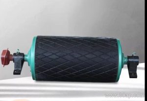
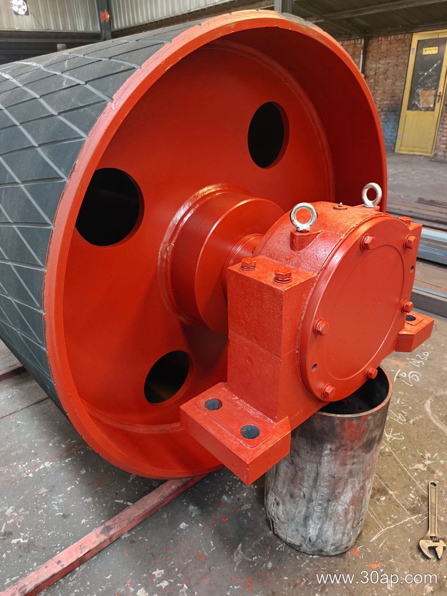
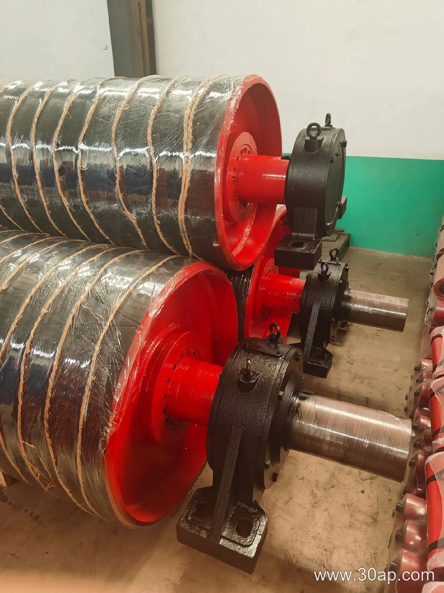
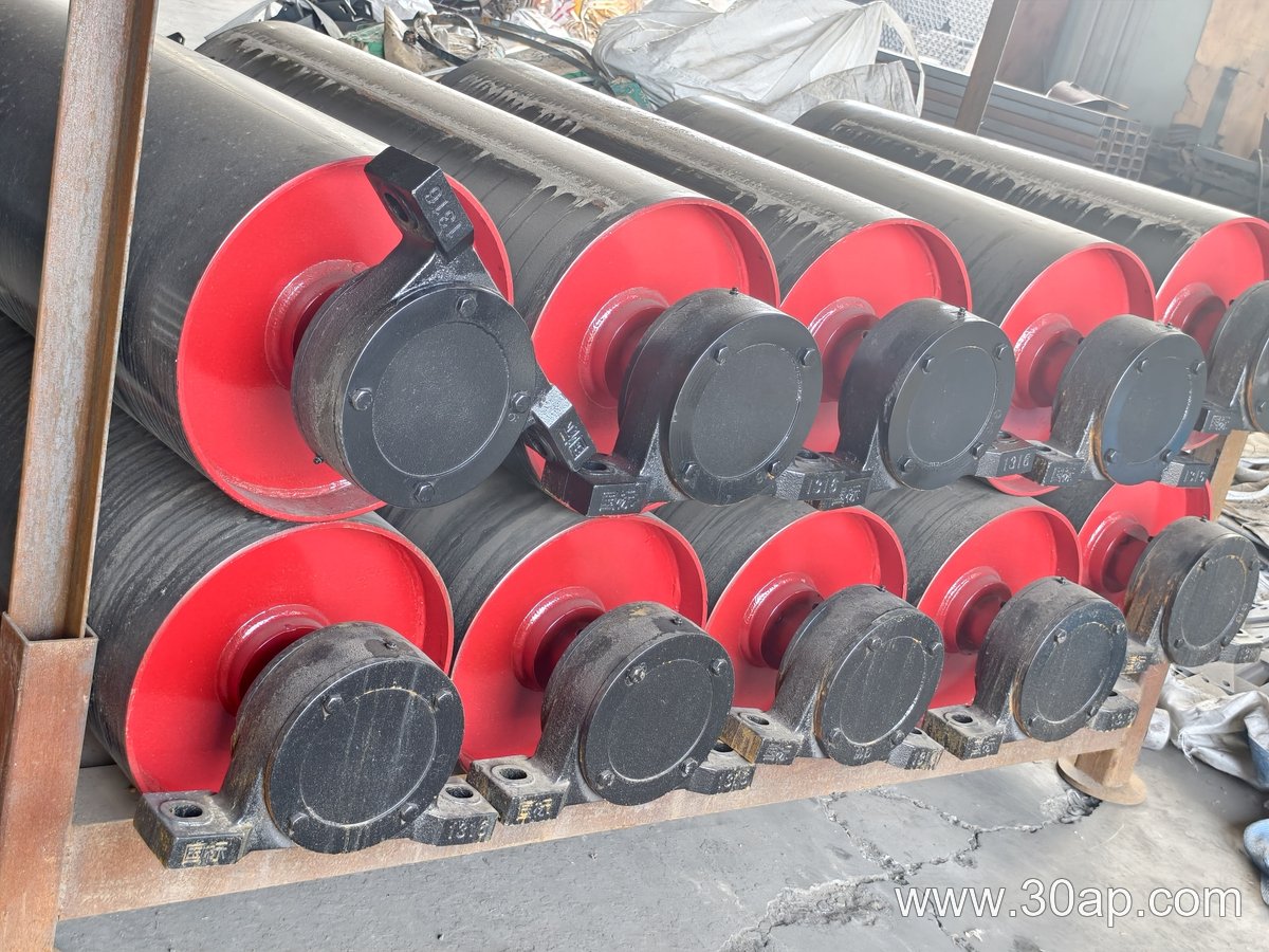
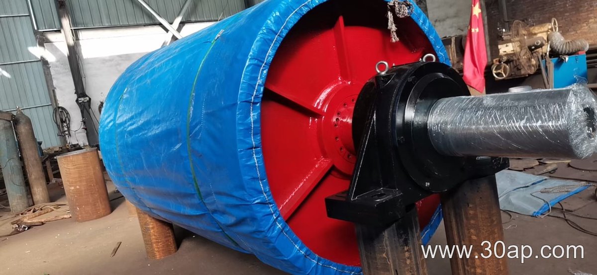
A typical unit consists of a steel drum shell, two end discs, a through shaft, hubs, and bearing housings. The shell is machined or rolled to a true diameter so the belt runs without vibration. Shafts are sized by torque and bending load, not by belt width alone. Common shaft diameters include Ø50, Ø60, Ø70, Ø80, Ø90, Ø100, Ø120, Ø140, Ø160, Ø180, and Ø200 mm, but the final value depends on the drive power, belt tension, and pulley mass. Bearings are usually spherical roller types mounted in pillow blocks or flanged housings, and the whole assembly is fixed to the conveyor bracket or frame with bolts and take-up provisions where needed.
Surface Options and Lagging
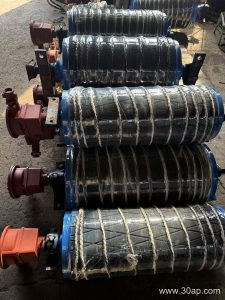
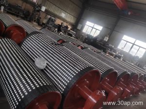
To improve grip between the drum and the belt, the face may be plain, cast rubber, cold-bonded rubber, hot vulcanized rubber, diamond grooved, herringbone grooved, ceramic lagged, or flat rubber. Lagging thickness commonly runs 8, 10, 12, 15, or 20 mm. Diamond and herringbone patterns help shed water and fine material, which is useful in sand and gravel lines or tunnel muck handling. Ceramic lagging is chosen where abrasion is severe. The right surface depends on the material, moisture, and the required friction coefficient, not on a single universal rule.
Common Sizes and Dimensional Relationships
Head pulley diameters are often matched to belt width and belt type. Typical diameters include Ø200, Ø250, Ø315, Ø320, Ø400, Ø500, Ø630, Ø800, Ø1000, Ø1250, Ø1400, Ø1600, and Ø1800 mm. Face width usually exceeds belt width so the belt is fully supported. For example, a B400 belt may use about 500 mm face, B500 about 600 mm, B650 about 750 mm, B800 about 950 mm, B1000 about 1150 mm, B1200 about 1400 mm, B1400 about 1600 mm, B1600 about 1800 mm, B1800 about 2000 mm, and B2000 about 2200 mm. These are reference values, not fixed pairings. A B1200 conveyor might use a Ø1000 mm head pulley, while a B800 unit could run a Ø500 mm drum. The diameter should be checked against belt ply, tension, and wrap angle.
Where It Is Used
You will find this component in limestone mines, iron ore plants, coal preparation facilities, power station coal handling, cement clinker lines, port bulk terminals, and aggregate crushing circuits. It works with the conveyor belt, idler rollers, and conveyor pulley assemblies to keep material moving. In some transfer points, a bend pulley or tail pulley is also present, but those are separate functions. The head pulley is the driven unit at the discharge end; it is not a replacement for a tail pulley or a bend pulley, and each subtype has its own role.
What Buyers Should Check
- Confirm belt width, belt speed, and required power so the shaft and bearing size can be calculated properly.
- Check the face width against the belt width and the lagging type against the material being carried.
- Ask for the shaft diameter, bearing size, and keyway dimensions rather than assuming a fixed value from belt width.
- Review the mounting interface with the conveyor bracket and the take-up system at the head end.
- Consider wear parts such as lagging and bearings as maintenance items, and keep spare units where downtime is costly.
A well-chosen belt conveyor head pulley keeps the belt centered, reduces slip, and protects the conveyor belt from unnecessary wear. Whether the application is a sand and gravel pit, a fertilizer plant, or a grain silo, the same principles apply: match the drum to the duty, verify the shaft and bearings, and select a surface that suits the material.