What a Conveyor Support Leg Does
A conveyor support leg is the structural column that carries the weight of a belt conveyor at intermediate points along the run. It stands between the ground and the conveyor frame, holding the main beams, brackets and idler stations at the required elevation. Without these legs, the frame would sag under the combined load of the conveyor belt, the material being carried and the moving components themselves.
The same component is often called a conveyor stand or conveyor frame support in workshop drawings. Whatever name appears on the drawing, its job is the same: transfer vertical and lateral loads from the conveyor structure into the floor, foundation or steel platform below.
How the Leg Is Built
Most support legs are fabricated from structural steel rather than cast. Common materials include angle steel, channel steel and folded steel plate. The choice depends on the load, the height of the conveyor and the environment.
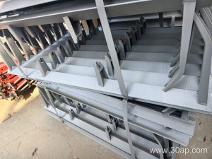
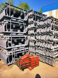
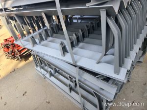
A typical leg assembly has a vertical post, a base plate with bolt holes, and a top connection that meets the conveyor stringer or cross beam. Some designs use a single post on each side, while wider belts may need a portal frame with two posts and a cross member. Adjustable versions include slotted holes or threaded sections so the frame height can be fine tuned during installation.
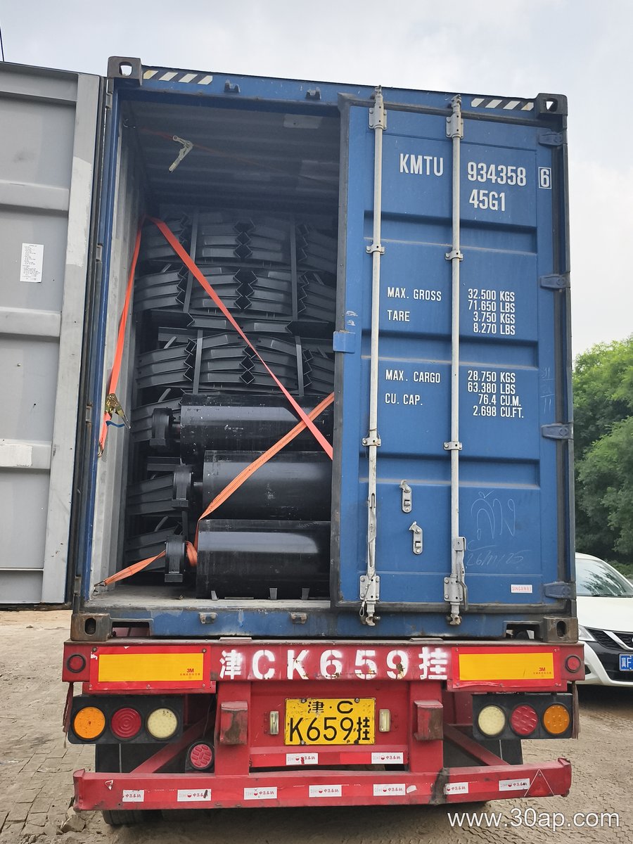
Surface treatment matters in wet or abrasive locations. Hot dip galvanizing and paint systems are both used, and the selection should match the site conditions rather than a default choice.
Where Support Legs Are Used
These legs appear wherever a conveyor runs above ground level. In a quarry or limestone mine, they hold the transfer and main haulage conveyors above the working floor. In a sand and gravel line, they support the inclined sections between the crusher and the screening plant. In a coal preparation plant or power station coal handling system, they carry the conveyor frame over walkways and equipment.
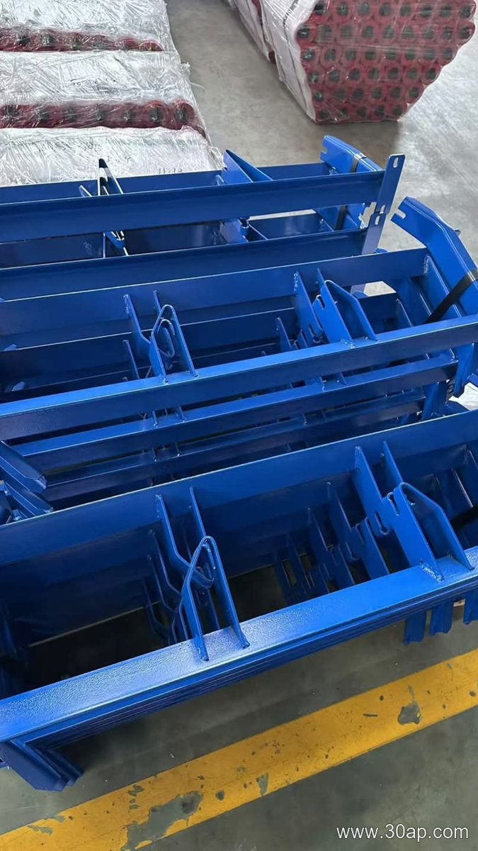
They are also used in cement plants, steel mills and port bulk terminals. The common factor is a need to keep the belt at a stable elevation while allowing access underneath for maintenance and material clearance.
Support Legs and the Components They Carry
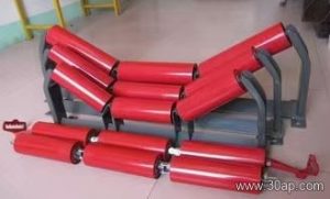
The leg does not work alone. It connects to a conveyor bracket that holds the idler roller or the troughing idler set. The bracket geometry follows the belt width and the trough angle, and the leg must be positioned so the idler sits at the correct height and alignment.
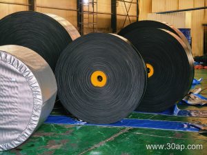
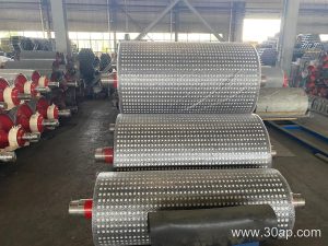
At the ends of a conveyor, the belt passes over a conveyor pulley, usually a drive pulley or a tail pulley. These pulleys are supported by their own heavier structures, and the support leg should not be confused with the pulley frame. A bend pulley, which changes belt direction without driving, is also supported separately. The leg is an intermediate support, not a substitute for any pulley support.
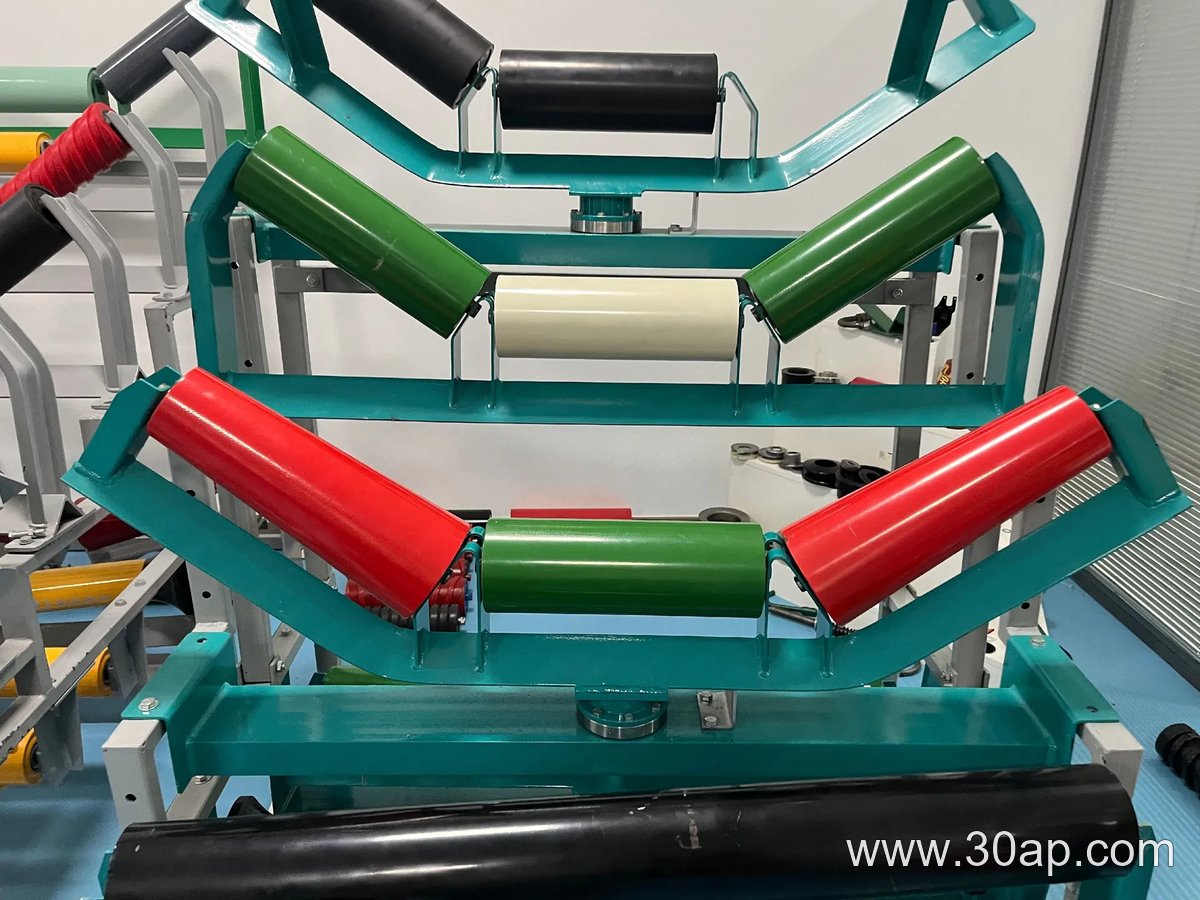
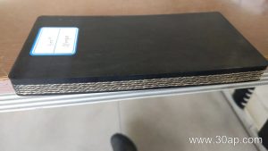
When the belt is loaded, the material weight passes through the conveyor belt into the idlers, then into the brackets and finally into the legs. This load path means the leg spacing and section size must be checked against the actual load, not assumed from belt width alone.
Types and Configurations
Support legs can be grouped by how they connect and adjust.
- Fixed legs: welded or bolted to a fixed height, used where the conveyor elevation is known and stable.
- Adjustable legs: allow height changes during installation or to compensate for floor unevenness.
- Single post legs: used on narrower conveyors and lighter loads.
- Portal or double post legs: used on wider belts and heavier material loads.
- Floor mounted and hanging versions: some structures suspend the frame from above, but the floor mounted leg remains the most common form.
Legs may also be paired with different bracket types depending on the station. A troughing bracket on the carrying side and a flat return bracket underneath may use the same leg, but the connection details differ.
What Buyers Should Check
Before ordering, confirm the belt width, the trough angle, the idler diameter and the conveyor height. These variables affect the leg height, the top connection and the bolt hole spacing. A leg made for one belt width may not fit another without modification.
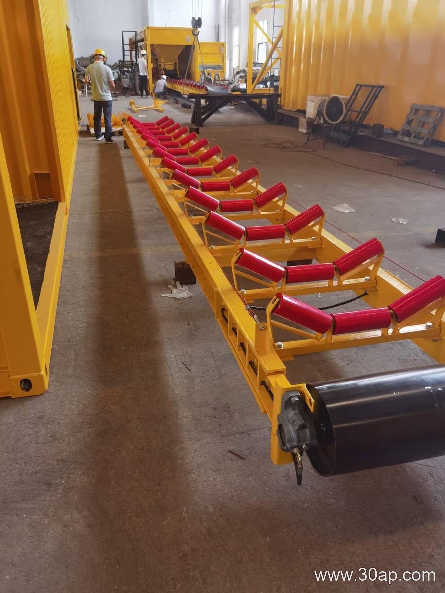
Common belt widths in conveyor design include B500, B650, B800, B1000, B1200, B1400, B1600, B1800, B2000 and B2200. Trough angles are often 20, 30, 35 or 45 degrees, and adjustable brackets can move between these angles. Idler diameters such as 89 mm, 108 mm, 133 mm, 159 mm and 194 mm are also common. None of these values should be treated as a fixed pairing; a B800 conveyor can use different trough angles and idler sizes depending on the duty.
Ask for the base plate hole pattern, the steel section used and the surface treatment. If the conveyor runs outdoors or in a washdown area, confirm that the coating suits the environment. Also check that the leg height matches the stringer elevation and that the top connection accepts the bracket or cross beam supplied with the conveyor.
Installation and Maintenance Notes
Set the base plates on level foundations and shim where necessary before tightening anchor bolts. Align the legs so the idler stations sit square to the belt centerline. Misaligned legs can cause the belt to track to one side and increase wear on the conveyor belt and idler roller.
Inspect legs periodically for loose bolts, corrosion and deformation. A bent leg changes the frame elevation and can affect belt tracking. Replacing a damaged leg with the correct section and height is simpler than trying to straighten it in place.