What a Conveyor Welded Pulley Is
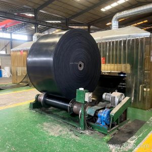
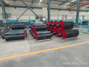
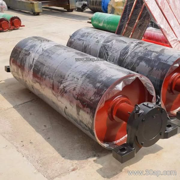
A conveyor welded pulley is a drum-shaped rotating component built up from a cylindrical shell, end discs, and a shaft, with the joints joined by welding rather than by bolting or shrink fitting alone. It carries and guides the conveyor belt at key points along a conveying line, and its welded construction gives the shell and hub assembly a continuous, rigid structure that suits heavy bulk handling. Buyers often meet this product under the equivalent name welded drum pulley, and both terms describe the same welded-shell drum.
The pulley is not a substitute for a drive pulley, tail pulley, or bend pulley; those are position-based roles, and a welded pulley can be supplied in any of them depending on the duty. What distinguishes it is how the body is fabricated and how that fabrication affects strength, balance, and service life.
How the Welded Body Is Built
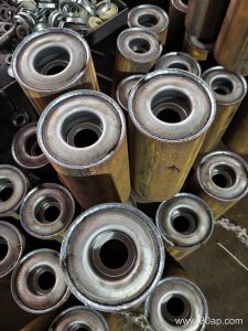
Production usually starts with rolled steel plate formed into a shell, which is then welded to machined end discs. The shaft passes through the hub and is fixed by welding or by a combined welded and keyed arrangement. After welding, the drum is machined and balanced so that the belt runs true at speed.
- Shell plate thickness is chosen according to belt tension and load, not by belt width alone.
- End discs and hubs transfer shaft torque into the shell.
- Shaft diameter is determined by torque and bearing loads; common shaft sizes include Ø50, Ø80, Ø120, and Ø160 mm, but the final value follows the design calculation.
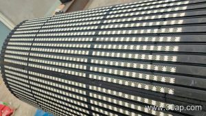
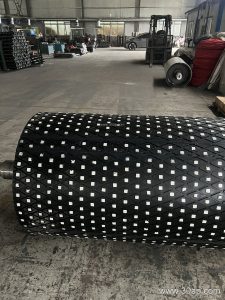
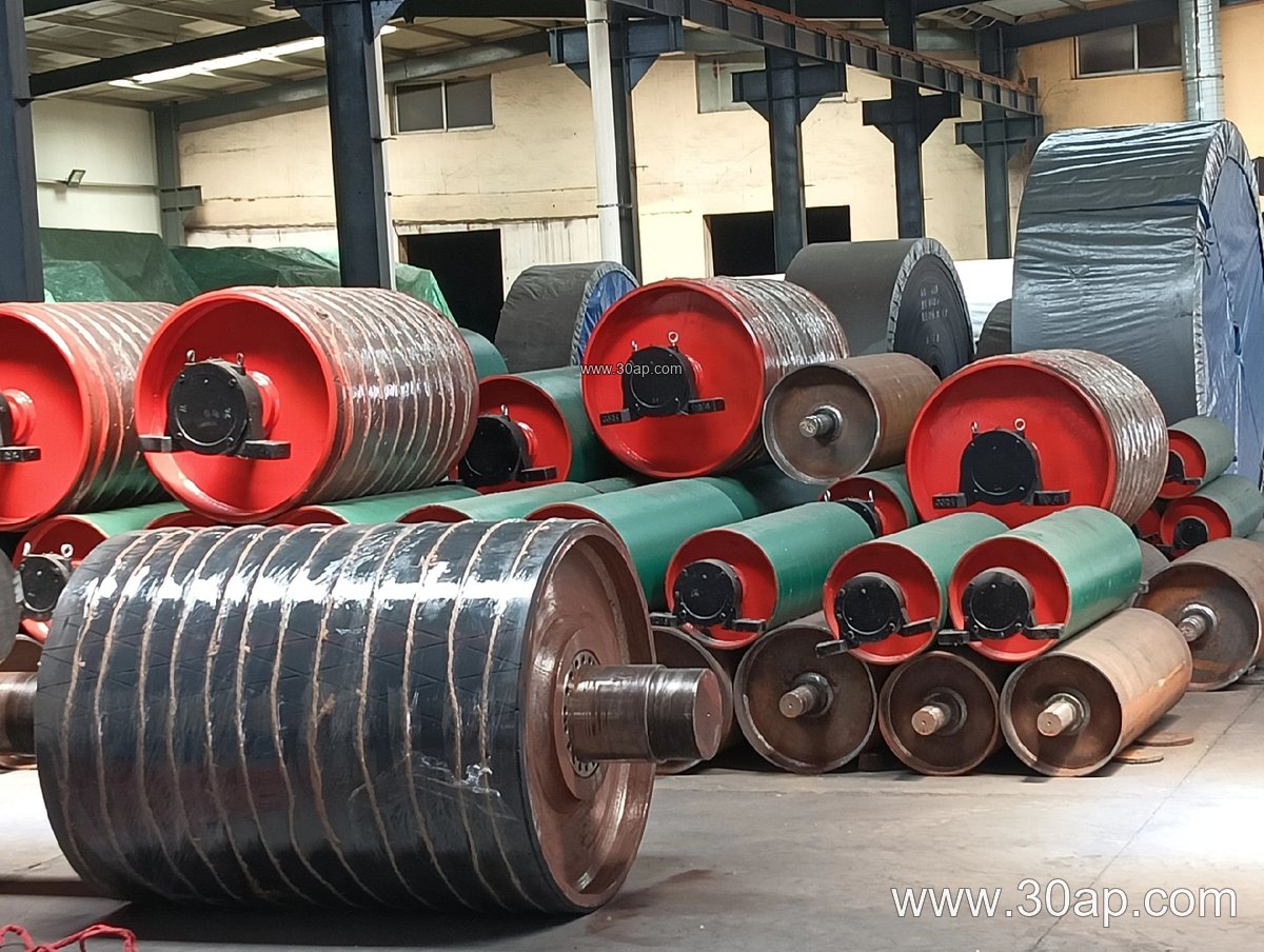
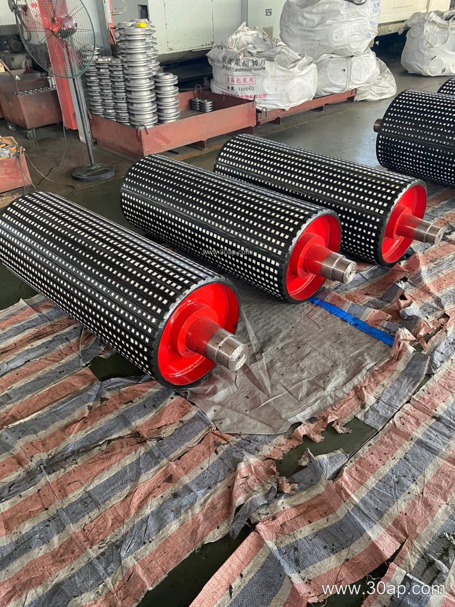
- Surface finish may be plain, rubber lagged, or ceramic lagged, with lagging thickness commonly 8, 10, 12, 15, or 20 mm.
Welding quality matters because weld defects can become fatigue origins under repeated bending. A buyer should ask for the welding procedure, inspection method, and dynamic balance report rather than accepting a visual check alone.
Where It Fits in a Conveying Line
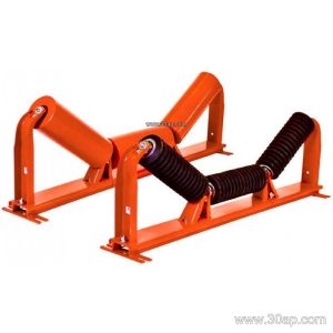
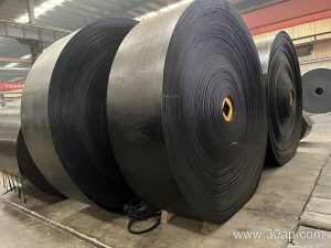
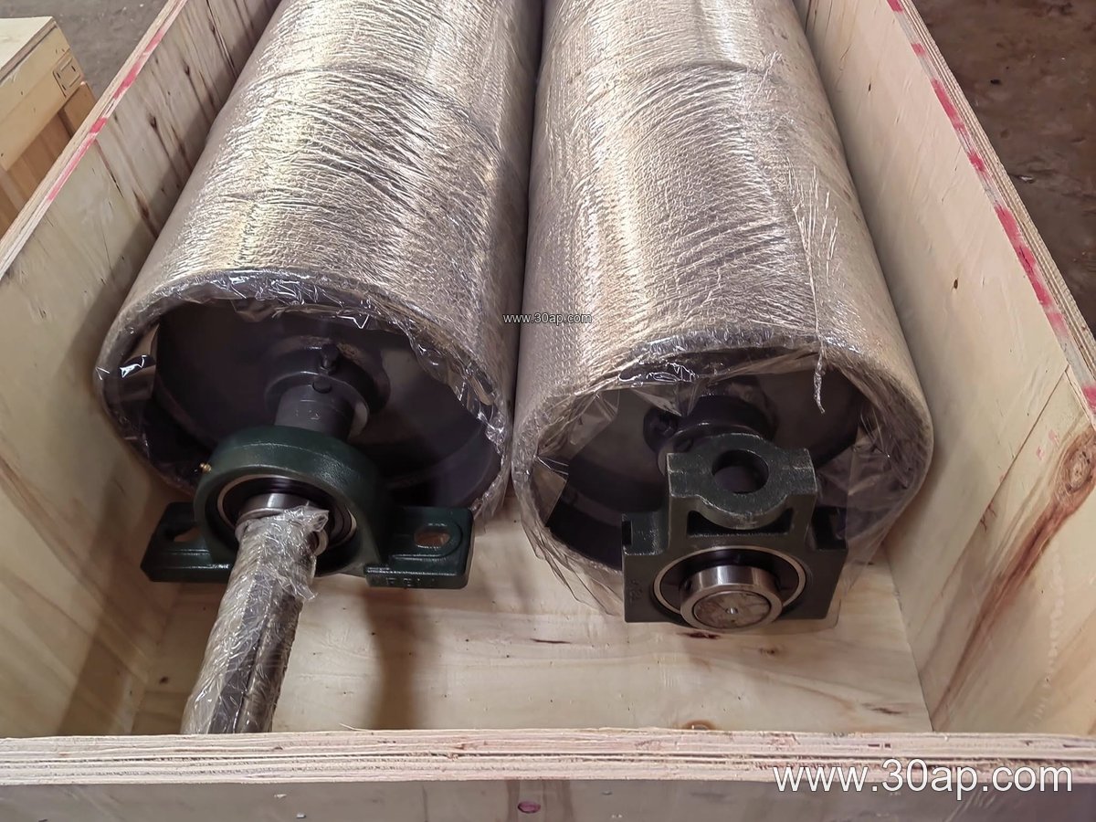
Welded drums appear at head, tail, tension, and snub positions. At the head end they discharge material and support the belt as it leaves the carrying run. At the tail they redirect the returning belt. Tension pulleys keep slack under control, while snub pulleys increase wrap angle around a drive drum. In a quarry or aggregate line, a welded pulley may work alongside a heavy-duty mining conveyor belt, impact idler rollers, and sturdy conveyor brackets.
In a coal washing plant or power station coal yard, a flame retardant conveyor belt is common, and the pulley surface and lagging should be selected to match the belt cover rather than simply copied from another line. In a cement plant, dust and fine abrasive material make lagging wear a regular maintenance item.
Matching Pulley Dimensions to the Belt
Shell face width is normally a little wider than the belt. For reference, a B400 belt often pairs with a face around 500 mm, B650 with about 750 mm, B800 with about 950 mm, B1000 with about 1150 mm, B1200 with about 1400 mm, and B1400 with about 1600 mm. These are common relationships, not fixed rules. A B1200 × Ø1000 drum and a B800 × Ø500 drum are both realistic combinations, but the diameter must be checked against belt tension, wrap angle, and the allowable bending stress in the shaft.
| Belt width | Typical face width | Example drum combination |
|---|---|---|
| B500 | about 600 mm | B500 × Ø400 |
| B800 | about 950 mm | B800 × Ø500 |
| B1000 | about 1150 mm | B1000 × Ø630 |
| B1200 | about 1400 mm | B1200 × Ø1000 |
| B1400 | about 1600 mm | B1400 × Ø800 |
Do not assume one belt width can only match one pulley diameter, and do not derive a shaft size from belt width alone. The same B1000 line may use different drum diameters at head and snub positions because the loads differ.
Surface Options and Material Pairing
Plain shells suit light duty and clean running. Rubber lagging improves grip and reduces belt slip; diamond or herringbone patterns help shed water and fines. Ceramic lagging is chosen where abrasive carryback wears plain rubber quickly. The lagging should be compatible with the belt: a heat resistant conveyor belt in a clinker or sinter application needs a drum surface that will not degrade at the same temperature, while an oil resistant conveyor belt calls for lagging that resists swelling.
For long overland or high-tension lines, a steel cord conveyor belt distributes load differently from a fabric core conveyor belt, and the pulley shell and shaft must be sized for the resulting tension. In fine bulk handling, a pipe conveyor belt or corrugated sidewall conveyor belt may need special drum geometry, so the pulley drawing should always follow the belt manufacturer’s data.
Buyer Checklist
- Confirm the position role: head, tail, tension, or snub. These are not interchangeable.
- Provide belt type, width, tension, and speed so the drum and shaft can be calculated.
- State the environment: coal dust, cement powder, iron ore, port humidity, or wash-down.
- Request weld inspection, balance grade, and lagging thickness in writing.
- Check bearing and bracket interfaces, plus shaft keyway dimensions, before ordering.
For drawing review and spare planning, our pulley and drum engineering pages at blmmfg.com/conveyor-pulley/ can be used as a starting reference, together with belt data from blmmfg.com/conveyor-belt/ and roller details from blmmfg.com/idler-roller/. A welded pulley that is correctly matched to its belt and duty will run quieter, track better, and last longer than one chosen by width alone.