What a Conveyor Belt Support Frame Does
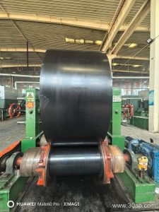
A conveyor belt support frame is the structural backbone that holds the idler rollers in the correct position along a conveyor. It keeps the belt profile stable, maintains the trough angle, and carries the load from the belt and material into the conveyor stringer or floor. In a quarry, coal preparation plant, cement kiln line, or power station coal yard, the support frame is the part that turns a loose collection of rollers into a working conveyor.
The frame is not the same as a conveyor pulley. Drive pulleys, tail pulleys, and bend pulleys transmit motion and change belt direction; the support frame only carries and guides the belt between those points. A conveyor bracket may connect the frame to the stringer, but the bracket is a fixing detail, not the frame itself.
How the Frame Is Built
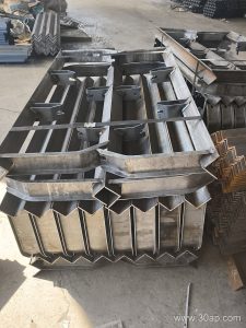
Most frames are fabricated from angle steel, channel steel, or folded steel plate. The crossbeam length and mounting hole spacing are determined by belt width and trough angle, so they are not fixed numbers. A typical assembly includes a crossbeam, two side brackets, and mounting slots for the idler roller shafts. On adjustable versions, the side brackets allow the trough angle to be set on site.
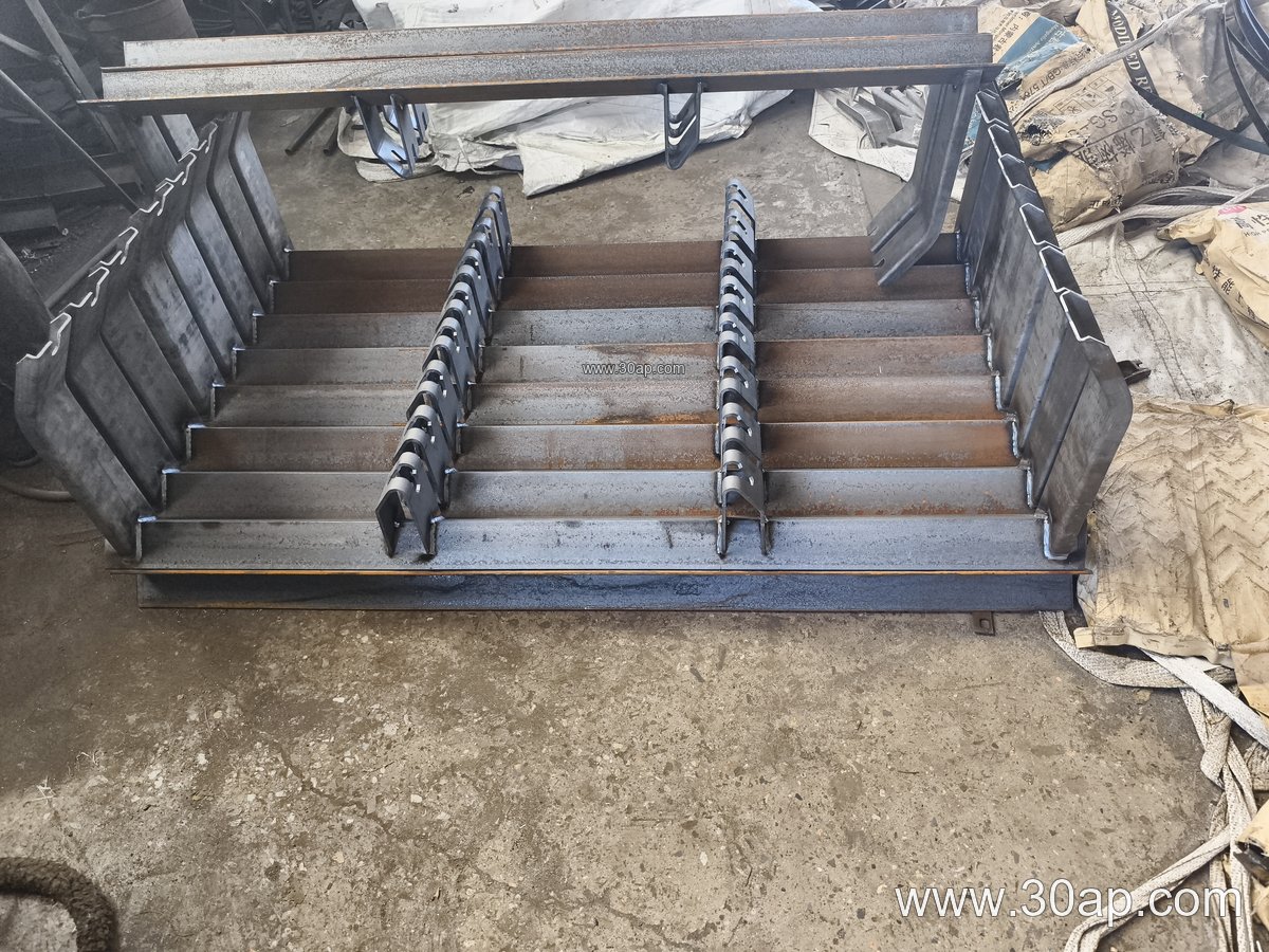
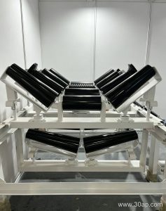
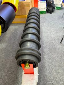
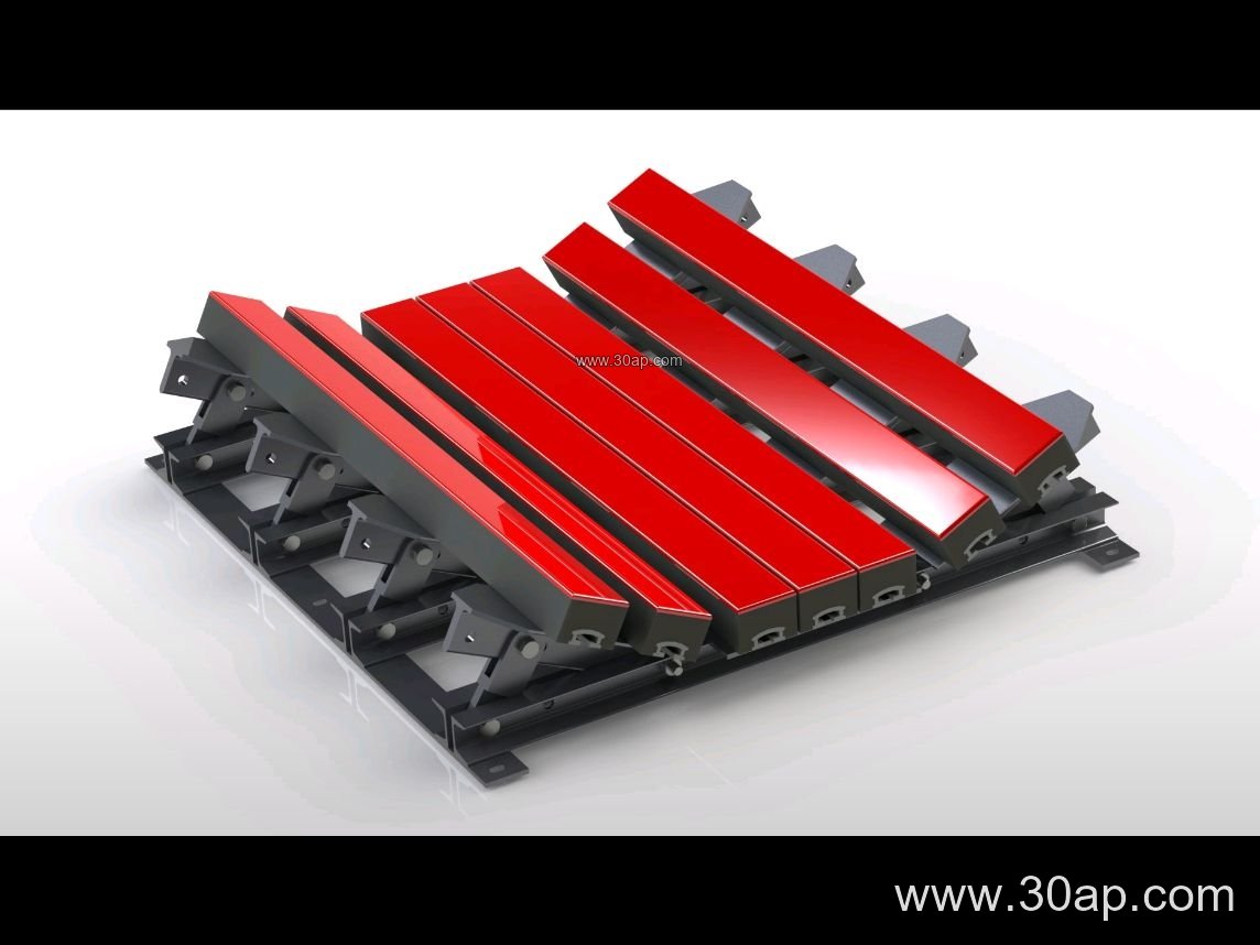
Common frame types include trough support frames for the carrying side, transition frames near pulleys, return frames for the empty side, V-return frames, impact frames under loading points, and self-aligning frames. Each type has a specific position on the conveyor and should not be swapped with another type without checking the belt line design.
Matching Belt Width, Trough Angle, and Roller Diameter
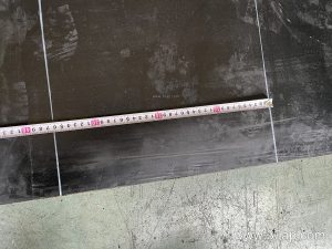
The support frame is selected together with the conveyor belt width, the required trough angle, and the idler roller diameter. Typical belt widths range from B500 to B2200, trough angles are commonly 20, 30, 35, or 45 degrees, and roller diameters include Ø89, Ø108, Ø133, Ø159, and Ø194. These values are reference data, not a fixed pairing rule. A B800 belt may run at 30 or 35 degrees with different roller diameters depending on load and speed; a B1200 frame may use 35 or 45 degrees for different material angles of repose. Adjustable frames allow the trough angle to be changed within the range.
| Frame Type | Typical Belt Width | Common Trough Angle | Common Roller Diameter |
|---|---|---|---|
| Trough support frame | B650 to B1800 | 20, 30, 35, 45 degrees | Ø89, Ø108, Ø133, Ø159 |
| Transition frame | B800 to B2000 | 20 to 35 degrees | Ø108, Ø133, Ø159 |
| Return frame | B500 to B1600 | Flat or V-return | Ø89, Ø108, Ø133 |
| Impact frame | B800 to B1800 | 30, 35, 45 degrees | Ø108, Ø133, Ø159 |
| Self-aligning frame | B650 to B1400 | 30, 35 degrees | Ø89, Ø108, Ø133 |
Frames with a forward tilt of about 1.5 to 2 degrees are used on some carrying idlers to help belt training. This is a frame feature, not a replacement for a self-aligning frame.
Where It Is Used
In a limestone mine or crushing and screening plant, trough frames carry the belt under coarse rock. In a coal washing plant, return frames and V-return frames support the clean side of the belt. In a cement plant, transition frames guide the belt as it leaves the tail pulley. In a power plant coal yard, impact frames sit under the loading chute. The same support frame family also appears in sand and gravel lines, steel sintering plants, and tunnel muck conveyors.
What a Buyer Should Check
- Belt width and trough angle, because these set the crossbeam length and mounting hole spacing.
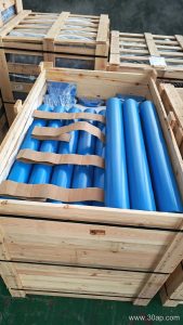
- Idler roller diameter and shaft fixing method, so the frame slots match the roller ends.
- Frame material and finish, especially for wet or dusty sites such as wash plants and ports.
- Whether the frame is fixed or adjustable, and whether the adjustment range covers the required trough angle.
- Compatibility with the conveyor bracket and stringer hole pattern on the existing line.
The support frame is a simple part, but it sets the belt line geometry. Getting the frame type, belt width, trough angle, and roller diameter aligned at the design stage avoids belt misalignment and premature roller wear later.