What a Conveyor Bracket Assembly Does
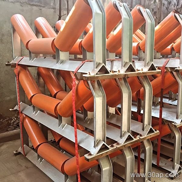
A conveyor bracket assembly is the structural interface that holds idler rollers in the correct position under or over a conveyor belt. It is not a single piece of hardware but a complete unit: a crossbeam, mounting plates, gussets, and drilled holes that accept idler shafts. In a quarry, a coal washing plant, or a cement kiln feed line, these assemblies define the trough shape that keeps material centered on the belt. The same term can refer to a fixed support or an adjustable one, but the core function remains the same.
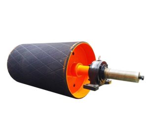
The assembly works together with the conveyor belt, idler roller, and conveyor pulley. While a drive pulley or tail pulley pulls and tracks the belt, the bracket assembly simply supports it between those pulleys. That distinction matters because a tail pulley and a bend pulley are not interchangeable with each other, and neither of them replaces the bracket assembly.
Construction and Common Materials
Fabricators typically build these units from angle steel, channel steel, or folded steel plate. The choice depends on load, belt width, and the environment. A crushed stone line with heavy impact may use thicker channel, while a grain silo or fertilizer plant may prefer a lighter folded design. Mounting holes are spaced according to belt width and trough angle, so the hole pattern is not universal.
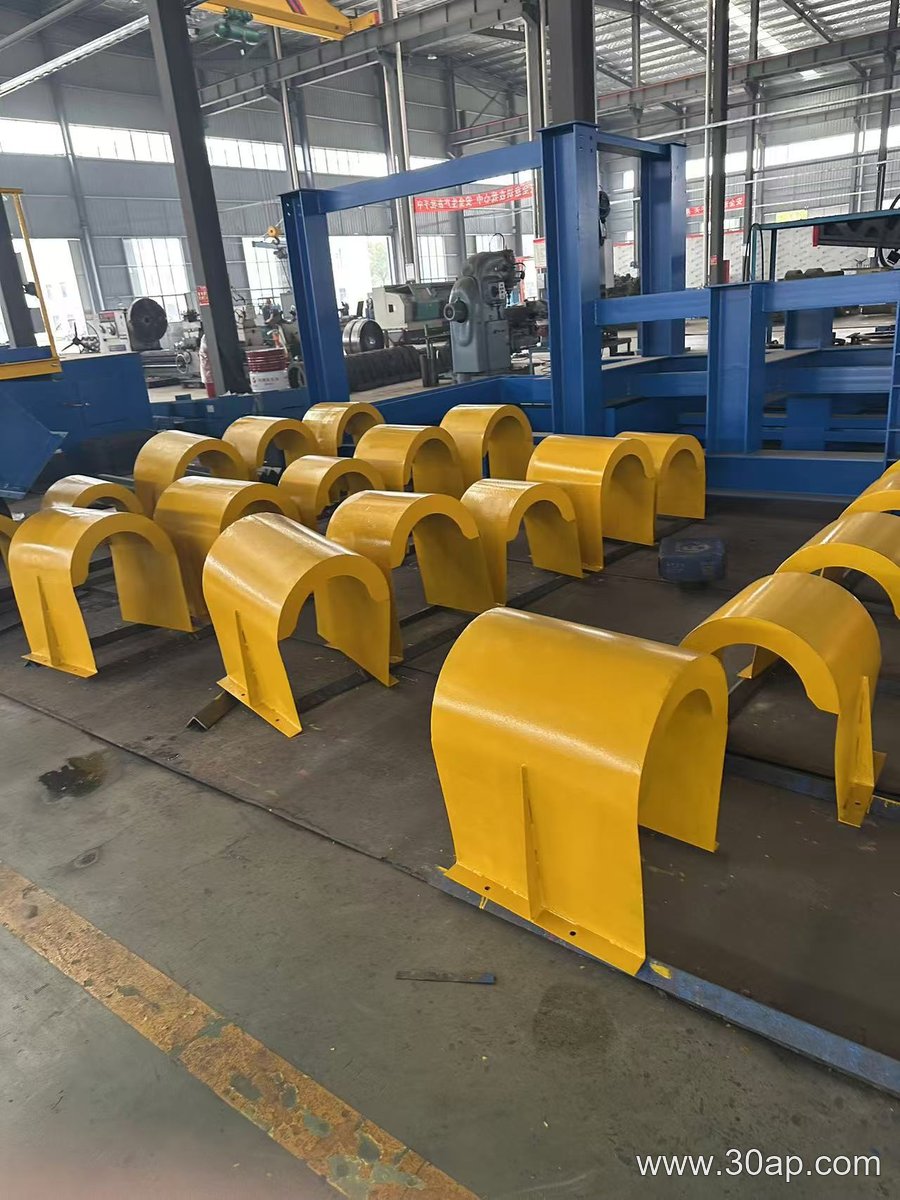
Common surface treatments include painting or galvanizing, though the exact finish depends on the supplier and the site conditions. The assembly may also include slotted holes for field adjustment, especially on transition or adjustable brackets.
Types and Where They Fit
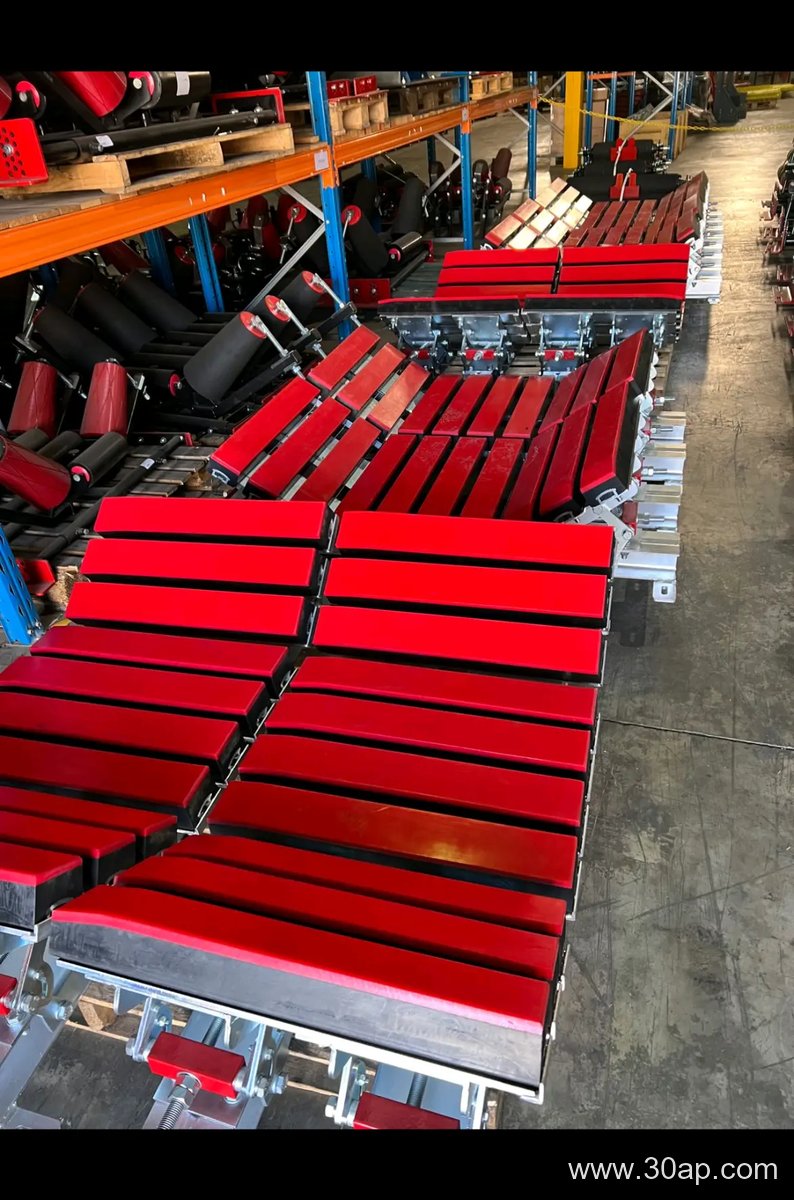
Different positions along the conveyor call for different bracket shapes. A trough bracket supports the carrying side and sets the trough angle. A return bracket supports the empty belt, sometimes with a V-shaped roller arrangement. An impact bracket sits under the loading zone to absorb force. A self-aligning bracket allows slight lateral movement to correct belt tracking. A transition bracket eases the belt from flat to troughed profile near a pulley. Each type is selected for its location, not as a replacement for another.
Parameters That Matter to a Buyer
When specifying a conveyor bracket assembly, the main variables are belt width, trough angle, and roller diameter. The table below shows common reference combinations, but these are examples, not fixed rules. Any belt width can work with more than one trough angle or roller diameter depending on the conveyor design.
| Belt Width | Common Trough Angle | Common Roller Diameter |
|---|---|---|
| B500 | 20° or 30° | Ø89 |
| B650 | 30° or 35° | Ø89 or Ø108 |
| B800 | 35° or 45° | Ø108 or Ø133 |
| B1000 | 35° or 45° | Ø133 or Ø159 |
| B1200 | 35° or 45° | Ø133 or Ø159 |
| B1400 | 35° or 45° | Ø159 or Ø194 |
| B1600 | 35° or 45° | Ø159 or Ø194 |
| B1800 | 35° or 45° | Ø194 |
| B2000 | 35° or 45° | Ø194 |
Installation hole spacing and crossbeam length change with belt width and trough angle. Do not assume a fixed shaft diameter from belt width alone. Forward tilt, often about 1.5° to 2°, is a separate feature and should be specified only when needed.
Selection and Maintenance Notes
- Match the bracket type to the belt position: carrying, return, impact, or transition.
- Confirm the roller shaft diameter and mounting hole pattern before ordering.
- For adjustable brackets, check the range of trough angles, such as 20° to 45°.
- Inspect for wear at the mounting slots and welds during regular belt maintenance.
- Keep spare assemblies for high-wear zones in iron ore, sinter, or tunnel muck conveyors.
A well-chosen conveyor bracket assembly keeps idlers aligned, reduces belt edge damage, and supports consistent material flow. The right unit depends on the conveyor layout, the material, and the surrounding equipment, not on a single universal size.