What the Idler Shaft Does
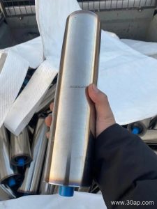
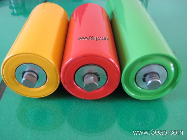
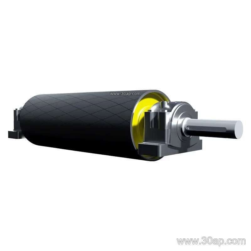
An idler shaft is the stationary axle inside a conveyor idler roller. It does not turn with the shell. Instead, the shell rotates on bearings mounted on this shaft, while the shaft itself is held fixed by the conveyor bracket at each end. In a belt conveyor line, dozens or even hundreds of these shafts sit under the carrying and return sides of the belt, quietly defining how freely the roller spins and how long the assembly lasts.
Because the shaft carries the full load transferred from the belt and material, it is a small part with a large responsibility. A shaft that is undersized, bent, or poorly machined will show up quickly as vibration, uneven belt tracking, or premature bearing failure. That is why buyers of conveyor components often treat shaft quality as a separate purchasing decision from the roller shell.
How an Idler Shaft Is Built
Most shafts start as round bar stock, commonly in carbon steel, and are machined at both ends to create bearing seats, retaining grooves, and flats or drilled ends for mounting. The middle section may be left at nominal diameter, while the ends are turned to a tolerance that matches the bearing bore. Some designs use a through shaft with a continuous diameter and separate bearing housings; others use stepped shafts that locate the bearings axially.
Surface finish matters. A rough bearing seat accelerates wear, and an out-of-round shaft will transfer that error to the bearing. Corrosion protection is equally important in wet or dusty service, so shafts are often painted, plated, or coated in the bearing area. For heavy-duty mining conveyor belt systems, shaft straightness and concentricity are usually checked before assembly.
- Material: usually carbon steel, sometimes stainless for food or chemical duty
- End features: bearing seats, grooves, flats, threaded or drilled ends
- Mounting: fixed into the conveyor bracket on both sides of the frame
- Fit: bearing bore matched to the machined seat, not to the shell diameter
Where Idler Shafts Are Used
The shaft is common to every roller type, but the working environment changes the specification. In a limestone quarry or a sand and aggregate line, dust and grit are the main enemies, so sealing and shaft finish get close attention. In a coal preparation plant or a power plant coal handling system, the belt may run continuously and the shaft must hold alignment over long operating hours. Cement plants add heat and fine abrasive powder to the mix.
Roller position also affects shaft selection. Carrying idlers on the top run see the weight of the material, while return idlers on the bottom run mostly support the belt itself. A transition idler near a conveyor pulley may experience different loading than a standard troughing station. The shaft must suit the roller it serves, not a generic average.
Common Roller Sizes and Shaft Considerations
The shaft is matched to the roller diameter, bearing size, and belt width. The table below shows typical roller diameters and belt widths as reference points, not as fixed pairings. Final shaft dimensions should be confirmed by design.
| Roller Diameter | Typical Belt Width Range | Bearing Examples |
|---|---|---|
| Ø63 mm | B400 to B650 | 6204, 6205 |
| Ø76 mm | B500 to B800 | 6205 |
| Ø89 mm | B650 to B1000 | 6205, 6305 |
| Ø102 mm | B800 to B1200 | 6305, 6306 |
| Ø108 mm | B800 to B1400 | 6306 |
| Ø127 mm | B1000 to B1600 | 6306, 6308 |
| Ø133 mm | B1200 to B1800 | 6308 |
| Ø159 mm | B1400 to B2000 | 6308, 6310 |
| Ø178 mm | B1600 to B2200 | 6310 |
| Ø194 mm | B1800 to B2400 | 6310 |
| Ø219 mm | B2000 to B2400 | 6310 |
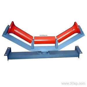
For a three-roll troughing set, roller length changes with belt width and trough angle. Common examples include about 200 mm for B500, 315 mm for B800, 465 mm for B1200, and 600 mm for B1600. Side rollers and center rollers can differ, so the shaft length is set by the roller drawing, not by belt width alone.
Buyer Checklist
When sourcing an idler shaft, ask for the drawing that defines bearing seat diameter, overall length, end configuration, material, and surface treatment. Confirm the bearing number and the roller shell it will serve. Check whether the application is a standard carrying idler, a return roller, or an impact position, because the load profile differs. For harsh service such as a copper ore or iron ore conveyor, specify corrosion protection and straightness requirements clearly.
Inspection should cover diameter tolerance at the bearing seats, runout, and thread or groove condition. A shaft that fits loosely in the bearing will wear both parts, and one that is too tight can damage the bearing during assembly. Spare shafts kept with the conveyor bracket hardware reduce downtime when a roller needs replacement.
Finally, remember that the shaft is one part of a system. Belt tension, pulley alignment, and roller spacing all influence how long it lasts. Matching shaft quality to the duty class of the conveyor is the most reliable way to avoid repeat failures.